Cooling structure of internal combustion engine

a technology of internal combustion engine and cooling structure, which is applied in the direction of engine cooling apparatus, liquid cooling, coolant flow control, etc., can solve the problems of unconsidered cooling of the cylinder head per se, and achieve the effect of improving the cooling performance of the recessed portion, efficient introduction into the recessed portion, and improving the cooling performance of the internal combustion engin

Active Publication Date: 2012-05-08
HONDA MOTOR CO LTD
View PDF12 Cites 6 Cited by
  • Summary
  • Abstract
  • Description
  • Claims
  • Application Information

AI Technical Summary

Benefits of technology

[0009]According to the cooling structure of the internal combustion engine, the cooling air introduction passage communicating from the cooling air passage to the recessed portion of the cylinder head is provided; therefore, cooling air can efficiently be introduced into the recessed portion to improve the cooling performance of the recessed portion. This can positively cool the plug seat disposed in the recessed portion and particularly subjected to high-temperature to improve the cooling performance of the internal combustion engine. Even while the vehicle is being parked and no cooling air flows into the cooling air passage, the cooling air introduction passage allows the cylinder block to communicate with the recessed portion of the cylinder head; therefore, convection flow occurs due to the increased temperature of neighboring air. This movement of air introduces fresh air into the recessed portion while heated air does not stay therein. Thus, cooling performance of the internal combustion engine can be improved during idling.
[0010]According to the cooling structure of the internal combustion engine, the cam chain chamber for housing a cam chain is formed at the cylinder-arrangement central portion, the cooling air introduction passage is disposed adjacently to the cam chain chamber, and the cylinder-arrangement end of the recessed portion is formed to open toward the outside. Therefore, cooling air can be led to the side of the cam chain chamber where air tends to stay in the recessed portion, thereby further improving cooling performance of the internal combustion engine. Since the cylinder-arrangement directional outer end of the recessed portion is formed to open outwardly, the negative pressure of running air acts on the opening portion of the recessed portion. This further promotes the introduction of cooling air from the cooling air introduction passage to further improve the cooling performance of the recessed portion.
[0011]According to the cooling structure of the internal combustion engine, the cooling air introduction passage can be formed between the cylinder bores and forward of and rearward of a line connecting cylinder centers. Therefore, between the cylinder bores can be cooled to improve the cooling performance of the internal combustion engine.
[0012]According to the cooling structure of the internal combustion engine, the cam shaft housing chamber is formed to overhang toward the recessed portion, and at least a portion of the cooling air introduction passage is formed at a position hidden by the overhanging portion of the camshaft housing chamber as viewed from the upper surface of the cylinder head. Therefore, the space of the recessed portion can be increased by the camshaft housing chamber formed to overhang toward the recessed portion, thereby increasing the surface area to enhance cooling performance. It is possible to introduce cooling air into the overhanging portion where air tends to stay in the recessed portion, which can further improve the cooling performance of the internal combustion engine.

Problems solved by technology

Because of this, cooling of the cylinder head per se has been unconsidered.

Method used


Image

  • Cooling structure of internal combustion engine
  • Cooling structure of internal combustion engine
  • Cooling structure of internal combustion engine

Examples


Embodiment Construction

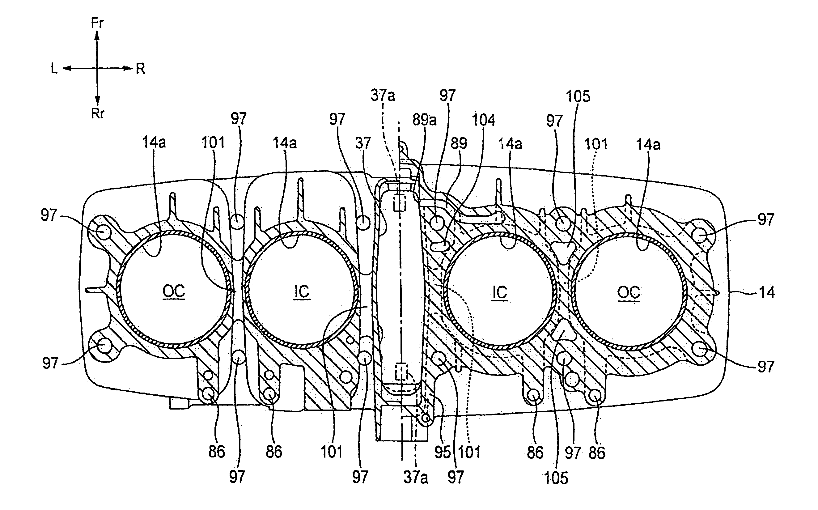
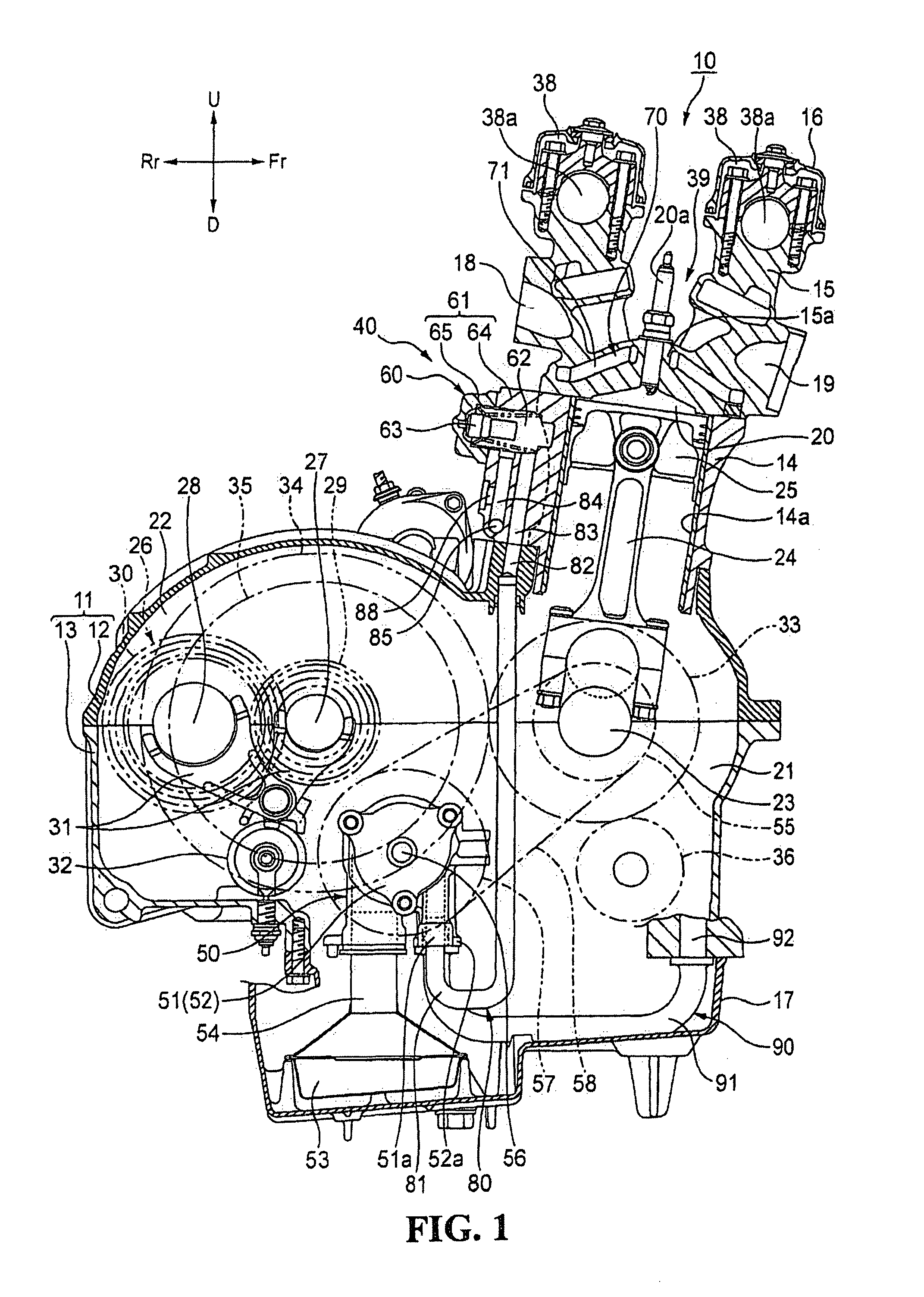
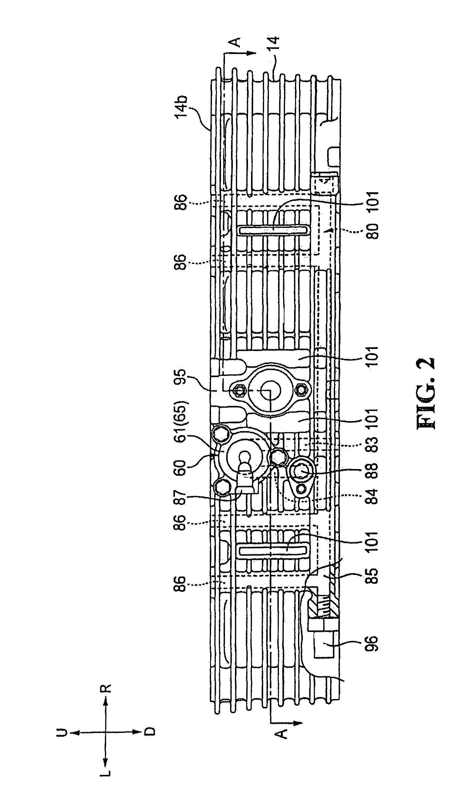
[0024]An embodiment of a cooling structure of an internal combustion engine according to the present invention will hereinafter be described in detail with reference to the accompanying drawings. Incidentally, the internal combustion engine of the present embodiment may be mounted on a motorcycle (not shown). In the following description, the front and back or rear, the left and right, and upside and downside are based on the direction a rider faces. In the drawings, the front, back or rear, left, right, upside and downside of a motorcycle are denoted with Fr, Rr, L, R, U and D, respectively.

[0025]The internal combustion engine 10 of the present embodiment is an in-line four-cylinder engine as shown in FIG. 1. An outer shell of the engine mainly includes a crankcase 11 composed of an upper crankcase 12 and a lower crankcase 13; a cylinder block 14 mounted to the front upper end of the crankcase 11; a cylinder head 15 mounted to the upper end of the cylinder block 14; a cylinder head...


PUM


Abstract

A cooling structure of an internal combustion engine includes a cylinder block having a plurality of cylinder bores; a cylinder head disposed on an upper portion of the cylinder block; two camshafts disposed on the cylinder head so as to be juxtaposed to each other in parallel to a crankshaft; camshaft housing chambers formed on the cylinder head to house the respective camshafts; a recessed portion provided between the camshaft housing chambers; a plug seat formed between the camshafts and in the recessed portion; a cooling air passage formed between the cylinder bores; and cooling air introduction passages communicating from the cooling air passage to the recessed portion of the cylinder head.

Description

TECHNICAL FIELD[0001]The present invention relates generally to a cooling structure of an internal combustion engine, and particularly, to a cooling structure of an internal combustion engine for a motorcycle.BACKGROUND OF THE INVENTION[0002]A traditional cooling structure of an internal combustion engine is known, in which a passage bored along a cylinder of a cylinder block having a plurality of cylinders allows an opening formed in a windward side surface of the cylinder block to communicate with an opening formed in an upper surface of the cylinder head, so that cooling air is guided between the cylinders and to the upper surface of the cylinder head (see e.g. Japanese Utility Model Laid-Open No. Sho 59-005711.[0003]Incidentally, the cooling structure of the internal combustion engine described in Japanese Utility Model Laid-Open No. Sho 59-005711 mentioned above aims to cool a position where the cylinders are adjacent to each other and is a technique of leading cooling air to t...

Claims


Application Information

Patent Timeline
Patent Type & Authority Patents(United States)
IPC IPC(8): F01P1/00
CPCF01P1/02
Inventor SUGIURA, HIROYUKI
Owner HONDA MOTOR CO LTD
Why Eureka
Try Eureka