Temperature monitoring

a technology of temperature monitoring and temperature, applied in the direction of instruments, de-icing equipment, transportation and packaging, etc., can solve the problems of compromising structural integrity, lack of robustness, and difficult lay-up and cure process

Inactive Publication Date: 2012-05-08
BAE SYSTEMS PLC
View PDF20 Cites 7 Cited by
  • Summary
  • Abstract
  • Description
  • Claims
  • Application Information

AI Technical Summary

Benefits of technology

[0010]The use of fibre-optics and their immunity to electro-magnetic interference effects and lightning strike provide considerable advantage over traditional metallic connections for standard discrete temperature sensors. Additionally, many temperature measurements can be made at multiple locations using a single optical fibre with a single connection. This drastically reduces the weight, complexity and component count when compared with the equivalent electrical measurement methods which comprise multiple thermocouples, each requiring individual cables and connections.
[0011]Where a plurality of heater mats are positioned adjacent one another, a continuous optical fibre strand may extend through and between each mat. In some circumstances, it may be desirable to connect together with appropriate connector elements shorter lengths of fibre to provide a single continuous fibre length. The continuous fibre sensor can then be used to determine temperature at arbitrary locations along its length and within the heater mats, thereby giving temperature distribution information across the heater mats. This temperature information is used to monitor potential overheat problems within the aircraft part or structure. This distributed sensing capability not only provides potential safety improvements (by monitoring a greater extent of the heater system than possible using discrete sensor technology) but also may assist in optimising heater mat power distributions.
[0013]The fibre-optic sensor arrangement in accordance with a preferred embodiment of the invention passes heater mat temperature information back to an ice protection system (IPS) control unit via a direct connection within the system wiring loom or through a sensor system data bus. The IPS control unit is able to control the electrical power distribution to the individual heater mats. The temperature information from the heaters enables the IPS control unit to monitor for overheat problems and react by managing the power distribution to the individual mats. The ability of the ice protection apparatus / system in accordance with embodiments of the invention to monitor efficiently all of the heater mat temperatures is likely to enhance the safety of the platforms in which it is installed as compared to known single sensor systems, and allow a measured response to any identified problems. The IPS control unit additionally has the potential, with the more extensive heater mat temperature monitoring of the invention, to adjust the power being distributed to each mat to obtain optimal performance in terms of minimum power consumption for achieving a given level of protection.
[0014]In accordance with embodiments of the invention, added safety benefits of monitoring the structure at many locations may be realised, together with the possibility of using temperature information to optimise the heater power distribution. Conveniently, the invention may be readily employed in test and development (either full-scale or wind-tunnel), where many more temperature sensing points are required to validate the design.
[0016]Optionally, a fibre-optic (FO) based sensor is incorporated in a heater mat formed of composite material. The FO sensor is embedded into the pre-form composite material, comprising either one of the layers of a composite structure incorporating electro-thermal heater mats prior to the curing process or into the composite based heater mat bonded to a metallic based structure. The ability to incorporate the fibre optic sensor into a composite lay-up greatly simplifies the manufacturing process, as compared to using discrete sensors, with the consistency of location being ensured and minimal compromise to the structural integrity. Further, because the robustness of optical fibres through the curing process has been effectively demonstrated with fibres being able to withstand the mechanical, chemical and thermal environments which can entail typical pressures and temperatures of 80 psi and 200° C. for autoclave cured carbon composites, the problem of sensors going inoperable during the manufacturing process is minimised.

Problems solved by technology

Commonly hot-air systems do not employ temperature monitoring equipment.
Integration of discrete sensors into composite structures may cause many problems during the manufacturing process.
Ensuring they are located at the correct location throughout the lay-up and cure process is problematic.
Their physical size can compromise the structural integrity and their lack of robustness is such that there are often significant numbers of inoperable sensors after the cure process.
The electrical connection to the sensors can be problematic with the added issue of electro-magnetic compatibility and interference.
Additionally, during test and development (either full-scale or wind-tunnel) many more temperature sensing points are required to validate the design, which compound these problems.
Given the problems associated with integrating each discrete sensor, known systems generally only monitor the structural temperature at what is perceived to be the single most critical location.
However other locations, where temperature-related problems may occur, may be significant.

Method used


Image

  • Temperature monitoring
  • Temperature monitoring
  • Temperature monitoring

Examples


Embodiment Construction

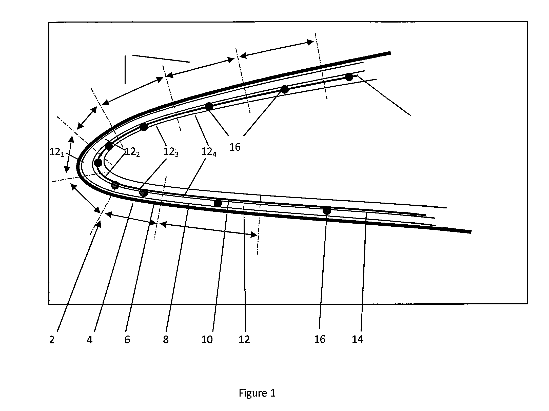
[0024]Referring first to FIG. 1, a leading edge slat 2 of an aircraft wing is defined by a contoured surface, which in this example is formed as an outer metallic erosion shield 4, inner layers 6, 10 of dielectric and structural composite material and a layer 8 of heater mats. The heater mats each extend a defined extent chord-wise, in a direction perpendicular to the length or span of the slat. Heater mats 121, 122, adjacent the leading edge, define what is known as a parting strip, where de-icing control is critical, and are smaller in width than heater mats 123, 124, etc., spaced from the leading edge. The width of each heater mat will be determined, inter alia, by the extent that de-icing considerations vary across the chord, and this will readily be determined by the person skilled in the art.

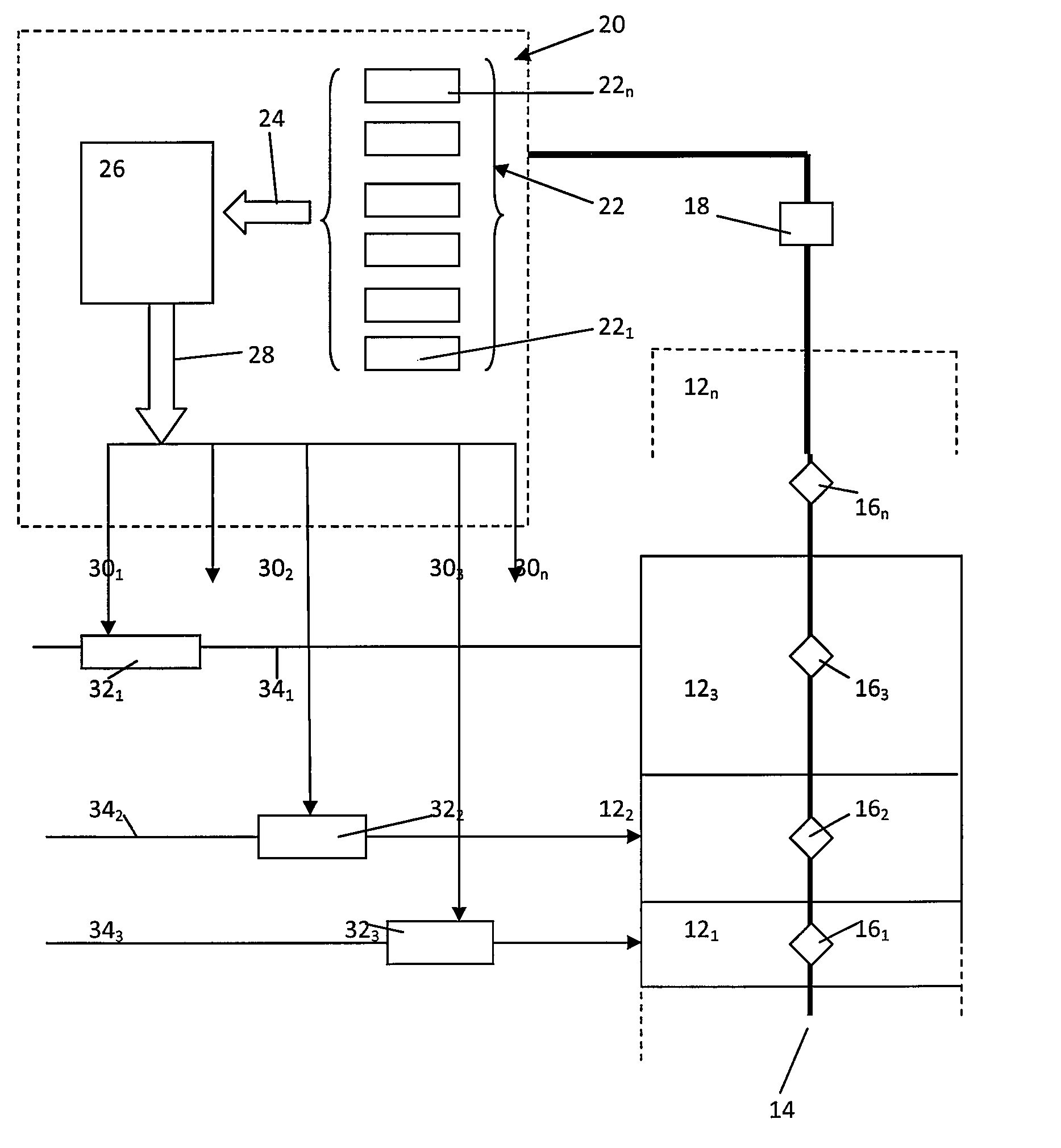
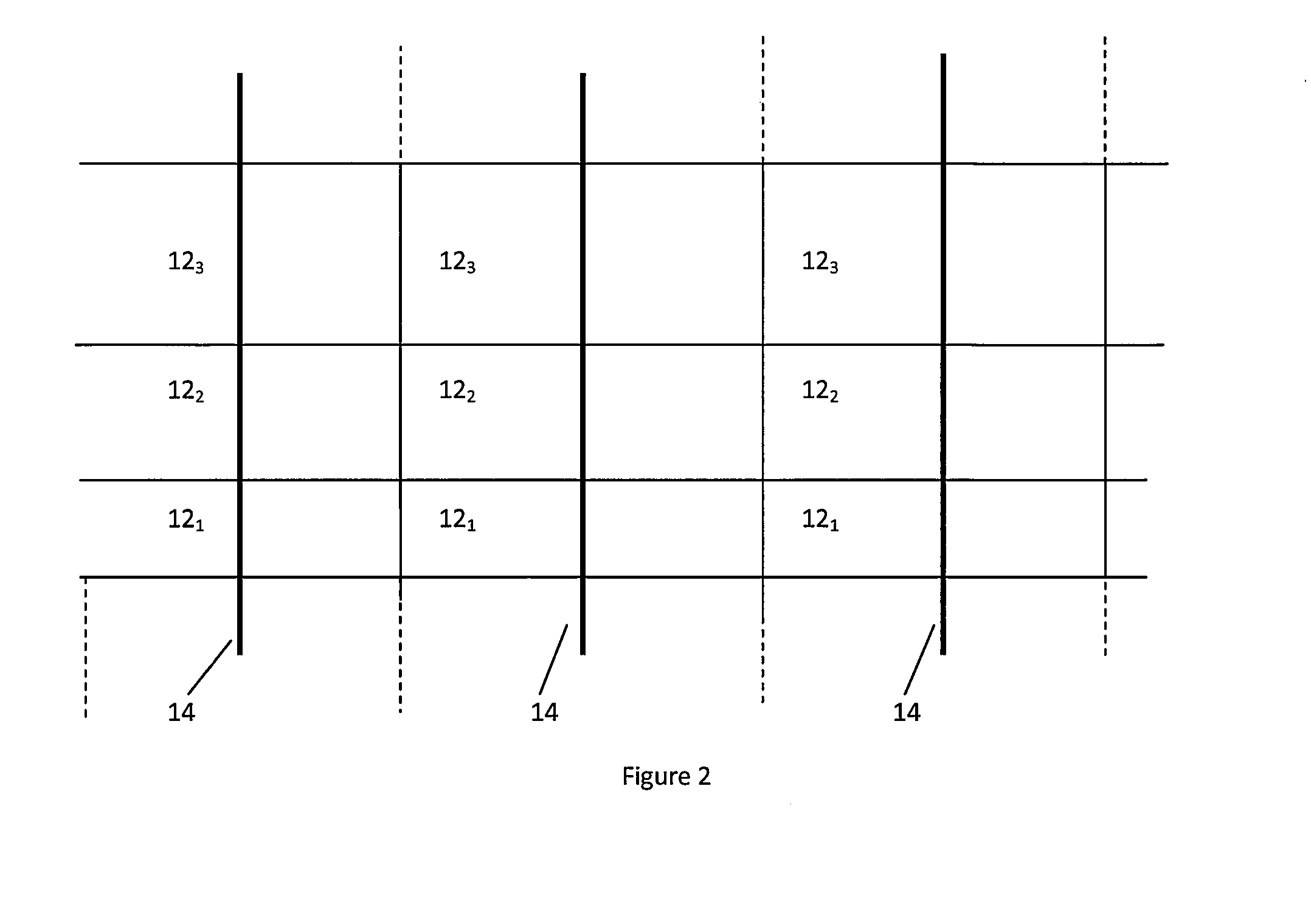
[0025]As shown diagrammatically in FIG. 2, a series of heater mats 121, 122, 123 etc., extend along the span or length of the slat, each mat having a predetermined length—as will be apprec...


PUM


Abstract

A temperature monitoring arrangement for an electro-thermal ice protection system is provided for a slat of an aircraft wing, incorporating heater mats of composite material, wherein, in order to avoid or at least substantially reduce some of the problems associated with use of discrete temperature sensing elements, one or more optical fiber temperature sensors are embedded within the heater mats for sensing an overheating condition of each mat. Advantageously, a control system is used to monitor the temperature of the mats, and adjusts power supplied, or switches off power, in response to detection of an overheating condition.

Description

CROSS REFERENCE TO RELATED APPLICATIONS[0001]This is the U.S. National Phase of PCT / GB2008 / 051133, filed Nov. 28, 2008, which claims priority to British Application No. 0723440.4, filed Nov. 30, 2007, and European Application No. 07270068.5, filed Nov. 30, 2007, the entire contents of all of which are incorporated herein by reference.FIELD OF THE INVENTION[0002]The present invention concerns improvements relating to temperature monitoring for detecting overheating conditions in electro-thermal ice protection systems for aircraft.BACKGROUND OF THE INVENTION[0003]Large commercial transport aircraft have traditionally utilised hot-air ice protection systems. The hot-air is supplied via bleed from the engines. Commonly hot-air systems do not employ temperature monitoring equipment. Electro-thermal heater systems previously have been widely used to provide ice protection to areas such as engine inlets and helicopter rotors. It has been proposed to use electrically powered heater mats int...

Claims


Application Information

Patent Timeline
Patent Type & Authority Patents(United States)
IPC IPC(8): B64D15/20
CPCB64D15/12B64D15/20
Inventor PRESS, ANDREW JULIAN
Owner BAE SYSTEMS PLC
Why Eureka
Try Eureka