Fuel filter

a technology of fuel filter and filter body, which is applied in the direction of filtration separation, machine/engine, separation process, etc., can solve the problems of difficult to properly constitute the filter body, limited number of layered filter materials, etc., and achieve the effect of improving the filtration accuracy of the fuel filter and a long-life fuel filter

Active Publication Date: 2012-05-08
NIFCO INC
View PDF169 Cites 36 Cited by
  • Summary
  • Abstract
  • Description
  • Claims
  • Application Information

AI Technical Summary

Benefits of technology

[0010]According to the present invention, without increasing the overlaid number of the filter materials due to the multifunctional filter material, an improvement of the filtration accuracy of the fuel filter and a long-life fuel filter can be attempted as much as possible. As a result, the fuel filter can be constituted easily and appropriately, and additionally at a low price.

Problems solved by technology

However, given the manufacturing cost of the filter body, the overlaid number of the filter materials is limited.
Also, the more the overlaid number of the filter materials, the number of the filter materials increases at a welded portion which is carried out in order to be bag-like, so that due to such welding, it is difficult to constitute the filter body appropriately.

Method used


Image

  • Fuel filter
  • Fuel filter
  • Fuel filter

Examples


Embodiment Construction

[0020]Hereinafter, embodiments for implementing the present invention will be explained with reference to FIGS. 1 to 9(b).

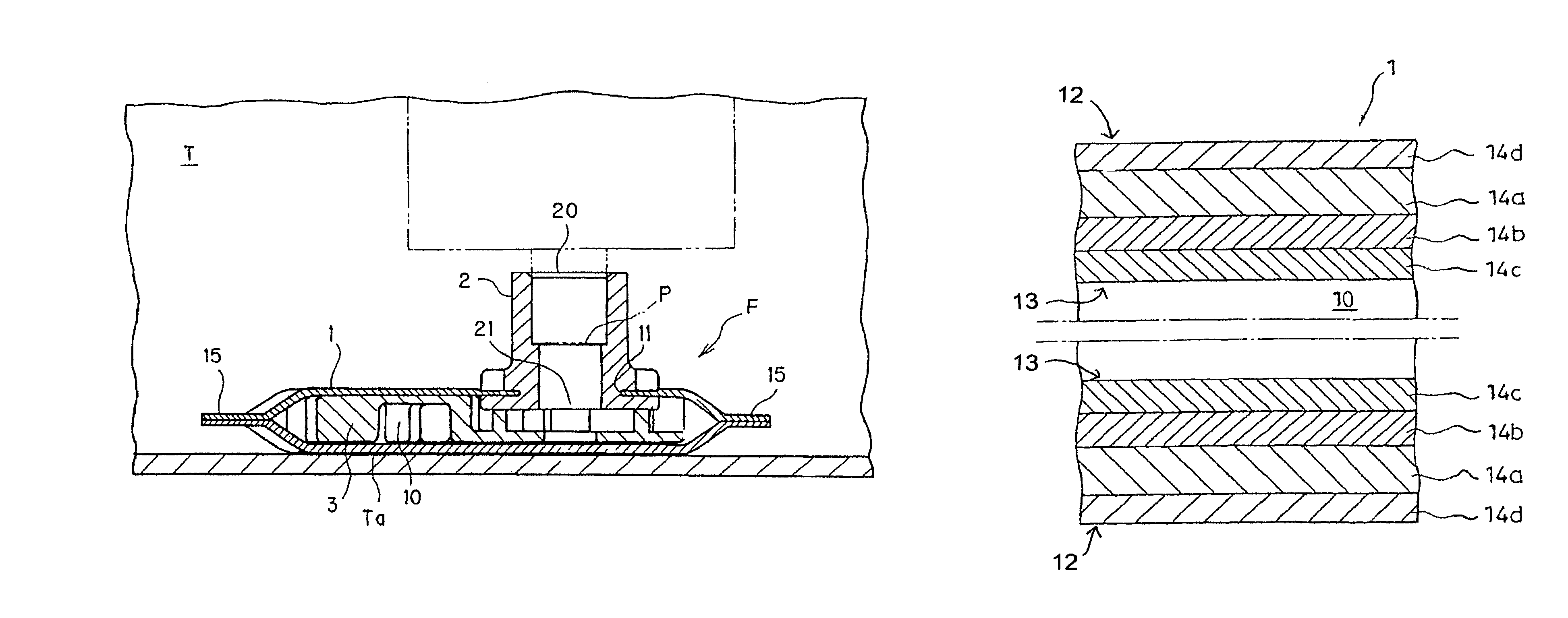
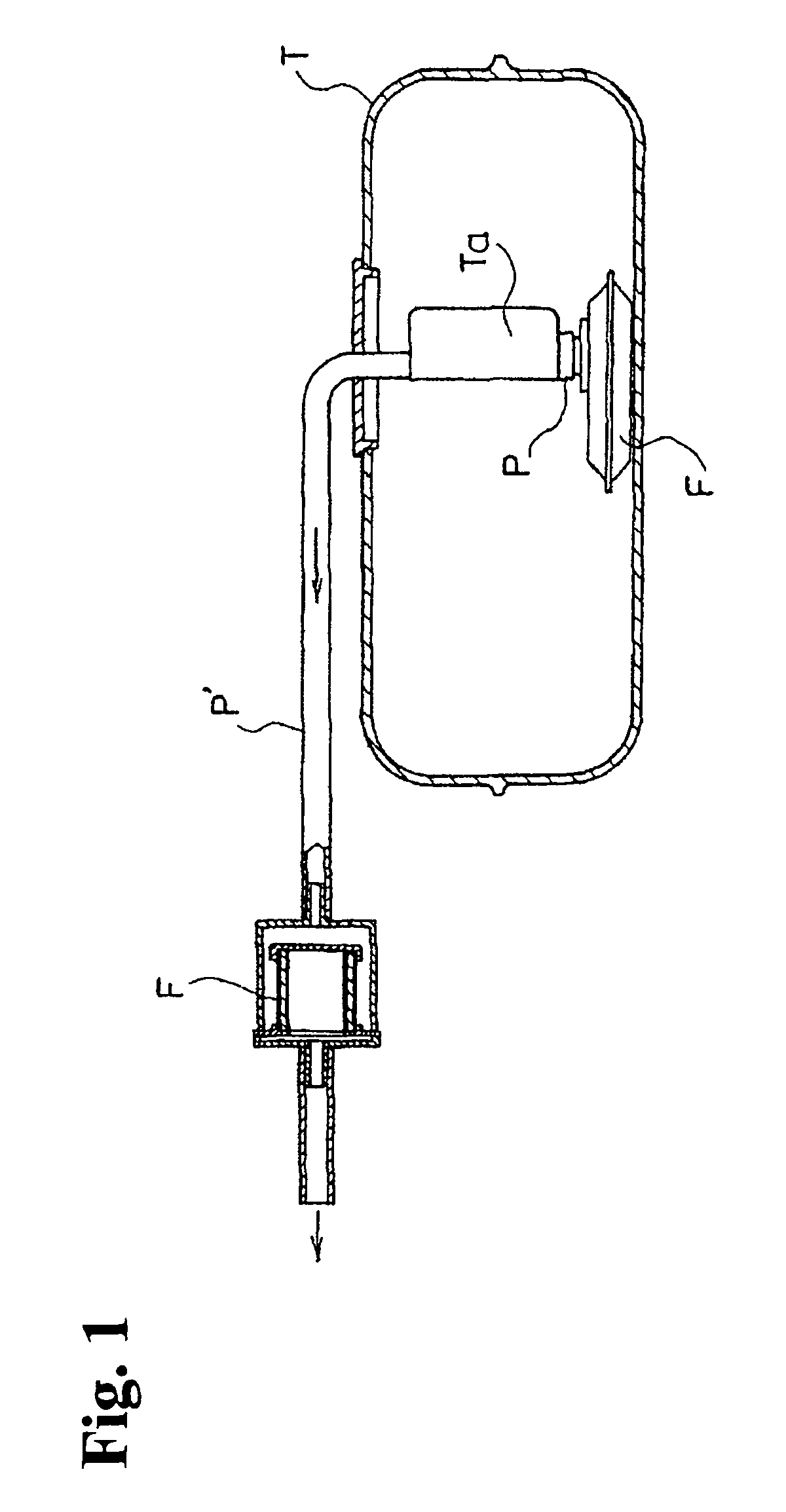
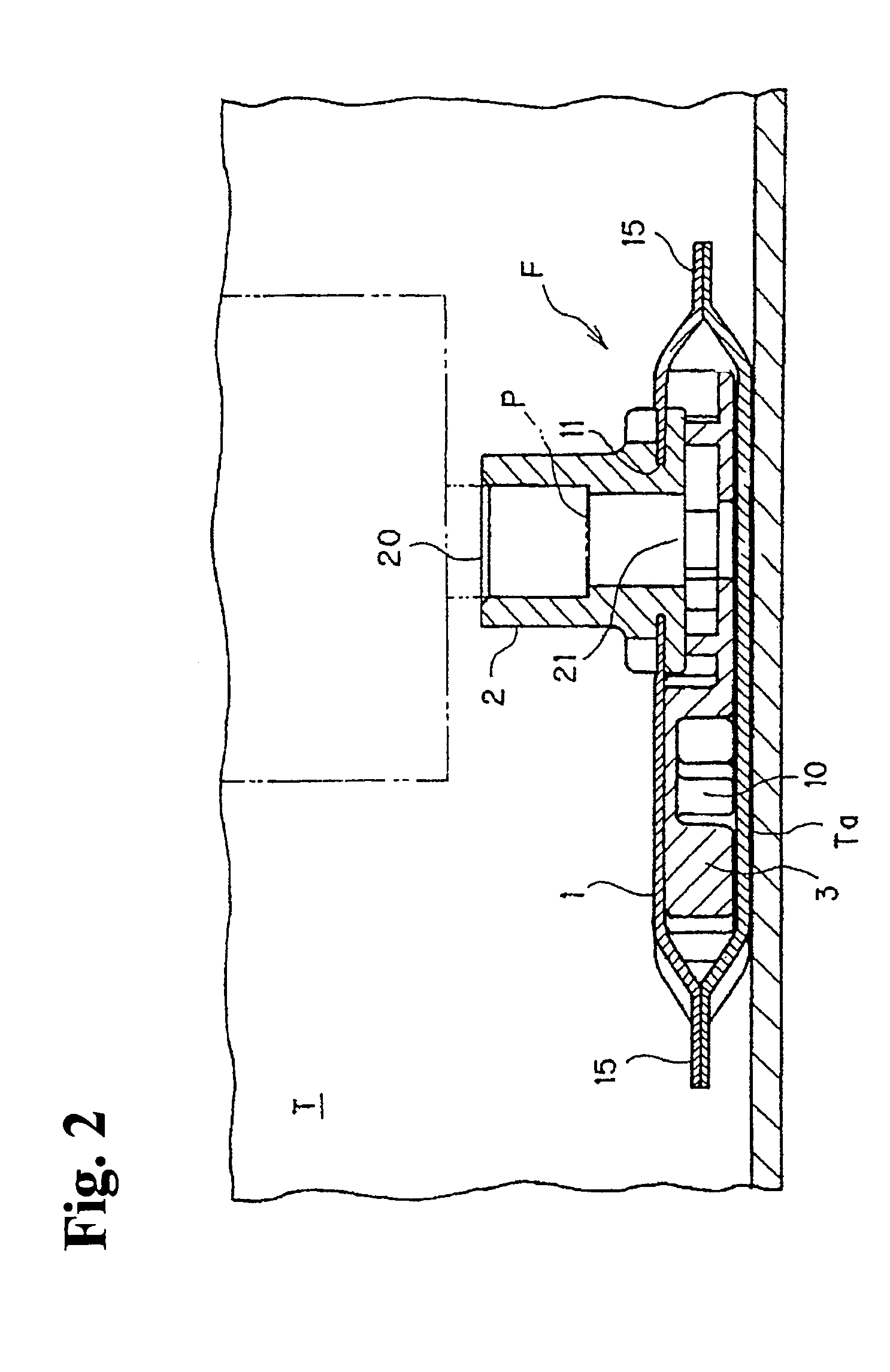
[0021]Incidentally, here, FIG. 1 shows a pattern diagram of a fuel tank T and one portion of a fuel line P′ so that a usage state of a fuel filter F constituted by applying the present invention can be easily understood. FIG. 2 is a structural view showing a state in which the fuel filter F is attached to a fuel suction port P located inside such fuel tank T. Also, FIG. 3 shows one example of a cross sectional structure of a filter main body 1 constituting such a filter device F. FIG. 4 shows another example of the cross sectional structure of the filter main body 1 structuring such filter device F. (FIGS. 3, 4 show only cross sectional structures of an upper surface side and a lower surface side of the filter main body 1, and the description of an interval formation member 3 housed inside the filter main body 1 is omitted.)

[0022]Also, FIGS. 5(a), 6(a), 7(a), 8(a...


PUM

PropertyMeasurementUnit
pore diameteraaaaaaaaaa
diameteraaaaaaaaaa
diameteraaaaaaaaaa

Abstract

Disclosed is a fuel filter in which is disposed in a fuel suction port of a fuel tank or in a fuel line and used to filter the fuel. At least one of filter materials constituting the fuel filter is made into a multifunctional filter material having a function of trapping dust of different particle diameters in stages, by differing the diameter of the pores in the filter material from the primary side to the secondary side of the filter material so that the size of the pores decreases toward the secondary side.

Description

FIELD OF TECHNOLOGY[0001]This invention relates to an improvement of a fuel filter used by being provided in a fuel suction port inside a fuel tank or in a fuel line.BACKGROUND ART[0002]The fuel inside the fuel tank is transferred to an internal combustion side through a suction pipe disposed inside the fuel tank and the like. In order to remove water from the fuel transferred in this manner and also prevent dust from being sent to a fuel pump, a filter device is attached to the fuel suction port and the like of such suction pipe. As such filter device, there is a filter device shown in Patent Document 1 disclosed by the present applicant.[0003]The filter device of the Patent Document 1 includes a bag-like filter body allowing an internal space to communicate with the fuel suction port located inside the fuel tank. Such filter body includes two layers of a filter material made of a non-woven fabric formed by a melt-blown method between the filter material of the outermost layer made...

Claims


Application Information

Patent Timeline
Patent Type & Authority Patents(United States)
IPC IPC(8): B01D29/13B01D29/15B01D35/02F02M37/22F02M37/24F02M37/34F02M37/50
CPCB01D35/0273F02M37/10F02M37/22B01D2239/0622B01D2239/0627B01D2239/065B01D2239/10F02M37/50F02M37/34F02M37/24F02M37/32
Inventor SATO, HIROJIUEKI, YASUSHIOGOSE, KENSUKE
Owner NIFCO INC
Why Eureka
Try Eureka