
Method and device for determining a distance to a target object

a target object and distance technology, applied in the field of distance determination to a target object, can solve the problems of low spatial resolution, unsuitability of such a distance determination, and inability to accurately determine the distance, so as to improve the range accuracy and increase the method's precision

Active Publication Date: 2012-05-08
VALEO SCHALTER & SENSOREN
View PDF12 Cites 0 Cited by
  • Summary
  • Abstract
  • Description
  • Claims
  • Application Information

AI Technical Summary

Benefits of technology

[0008]Through the reduction of the frequency of the incoming signal and the reference signal according to the invention by the pre-determinable divider factor, a magnification of the respective wavelengths of the incoming signal and of the reference signal corresponding to the divider factor is obtained, as a result of which the accuracy of the distance determination is likewise magnified. Thus, by means of the evaluation of the phase difference between the frequency-reduced reference signal and the frequency-reduced incoming signal, a distance determination can be carried out which is improved compared with the prior art.
[0010]In a particularly practical further embodiment of the present invention, the incoming signal and / or the reference signal is converted into a digital signal to obtain simple further processing of the respective signal and reduced susceptibility to errors compared with an analog signal. For conversion, a Schmitt-trigger or a comparator can e.g. be used. Suitably fast components with low divider factors, with even the already frequency-reduced signals still having frequencies in the gigahertz range, are e.g. obtainable from the field of optical telecommunications.
[0015]With a further very advantageous embodiment, different path lengths of the outgoing signal and / or of the incoming signal and / or of the reference signal and / or time delay differences of the signals caused, for example, preferably by an amplifier provided for amplification of the incoming signal and which occur within a device used for distance determination are compensated for.
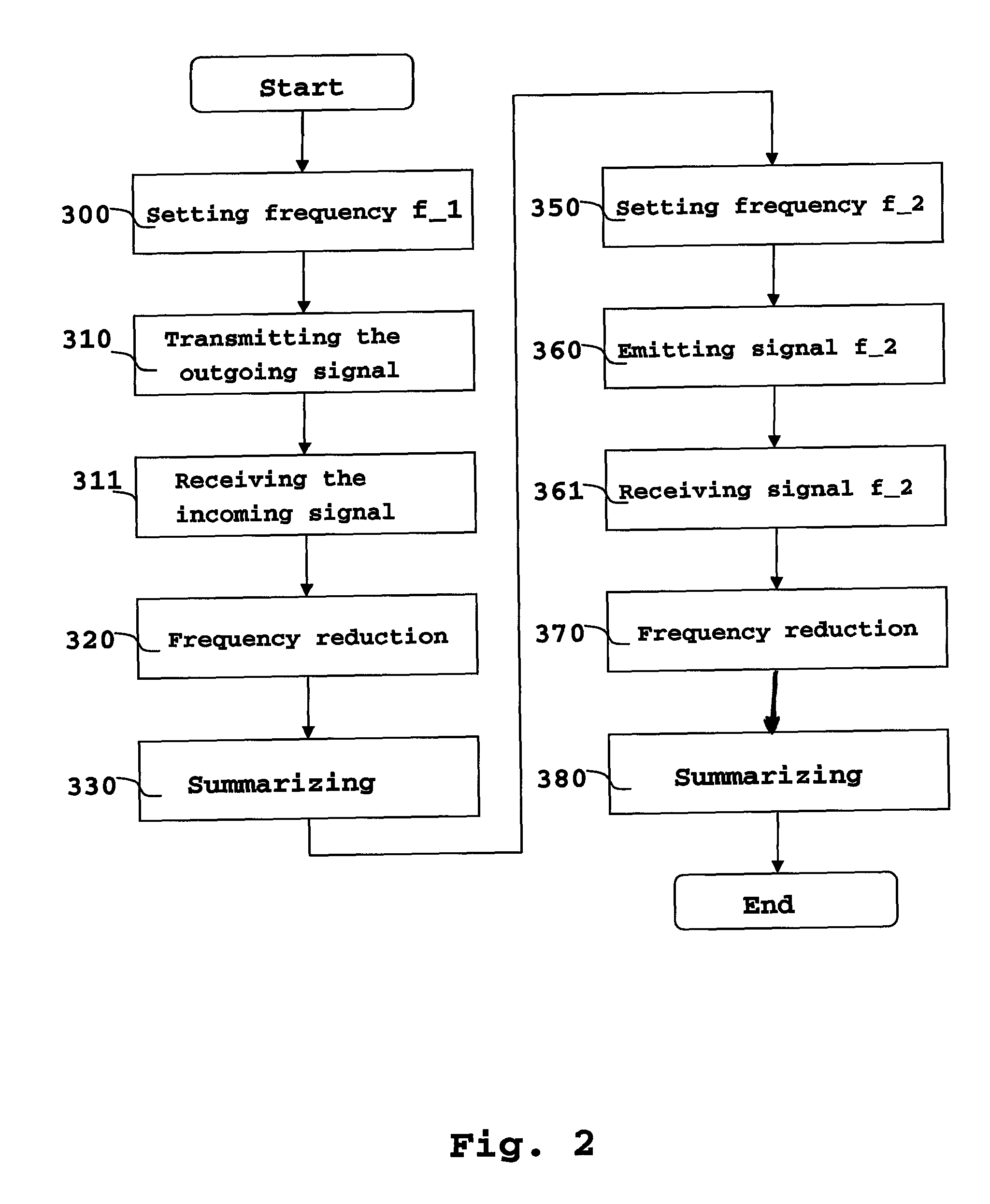
[0017]To further increase the precision of the method according to the invention it is proposed to successively transmit several outgoing signals with different frequencies. For example 2 outgoing signals of different frequency are sufficient to improve the range accuracy already magnified by the frequency dividing by the divider factor according to the invention during determination of the distance of the target object from the phase difference between the incoming signal and the reference signal.

Problems solved by technology

However, the accuracy of such a distance determination is only within one wavelength of the incoming signal used.
Particularly disadvantageous in this method is the spatial resolution for determination of the distance of the target object which, at a frequency of the outgoing signal of approximately 24 GHz and with a chirp bandwidth of approximately 200 MHz, amounts to only approximately 0.75 m. With a typical evaluation in the spectral range, position accuracies in the decimeter region can be achieved.
For many close-range applications, such as for distance detection in the field of motor vehicles, such low spatial resolution and position accuracy are unsuitable.

Method used


Image

  • Method and device for determining a distance to a target object
  • Method and device for determining a distance to a target object
  • Method and device for determining a distance to a target object

Examples


Embodiment Construction

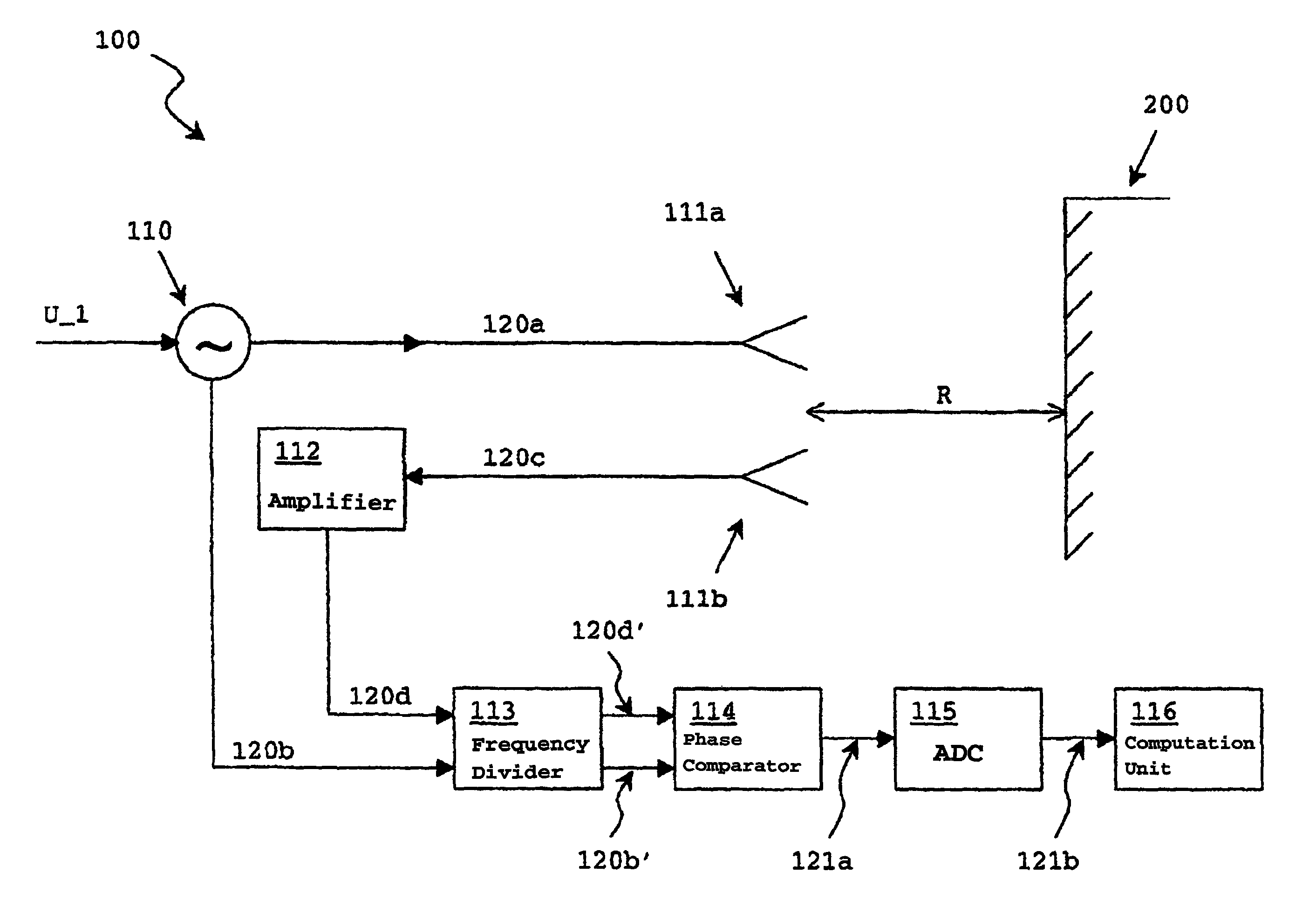
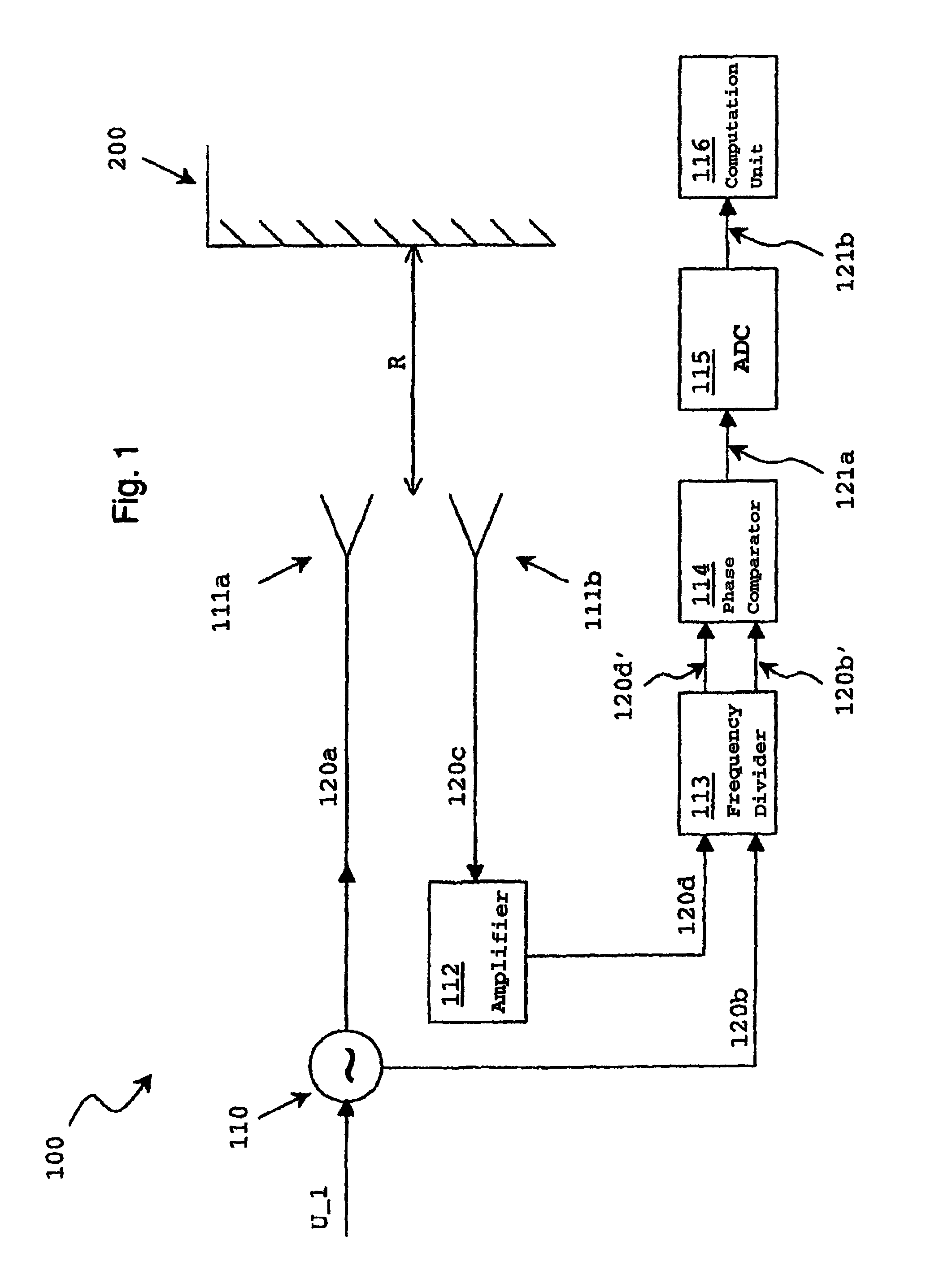
[0022]FIG. 1 shows a device 100 according to the invention, which is provided for determining a distance R to a target object 200. Towards this end, the device 100 has a transmitter 111a for transmitting electromagnetic waves in the form of an outgoing signal 120a supplied to the transmitter. The transmitter 111a can for example be a horn or a patch antenna. To amplify the outgoing signal 120a, the transmitter 111a can also have a high-frequency amplifier not shown in FIG. 1 if appropriate, which is connected upstream of the horn or patch antenna used.

[0023]The transmitter 111a irradiates the outgoing signal 120a onto the target object 200 and at least a part of that outgoing signal is reflected from the target object 200 and received in a receiver 111b. The signal received in the receiver, likewise having e.g. a horn or patch antenna, is called the incoming signal 120c in the further description.

[0024]According to the invention, the incoming signal 120c is supplied to an amplifier ...


PUM


Abstract

An apparatus and a method for determining a distance (r) to a target object (200) proposes transmitting electromagnetic waves in the form of a transmission signal (120a) by a transmitter (111a), receiving at least one part of said transmission signal (120a) reflected by a the target object (200) in the form of a reception signal (120c, 120d) by receiving device (111b) and evaluating the reception signal (120c, 120d) according a reference signal (1230b) which has a known phase difference with respect to the transmission signal (120a) and a frequency equal to the frequency thereof. The reference (120) and reception (120c, 120d) signal frequencies are reduced in a frequency divider (113) with the same predefined divider factor (x) while preserving the existing phase difference between the reference signal (120b) and the reception (120c, 120d) signal in such a way that a reduced frequency reception signal (120b′) and a reduced frequency reception signal (120d) are obtained. The frequency difference between the reduced frequency reception signal (120b′) and reduced frequency reception signal (120d′) is evaluated in order to determine the distance (R).

Description

[0001]This application is the national stage of PCT / EP2006 / 003910 filed on Apr. 27, 2006 and also claims Paris Convention priority of DE 10 2005 021 882.2 filed on May 4, 2005.BACKGROUND OF THE INVENTION[0002]The invention concerns a method for determining a distance to a target object, wherein electromagnetic waves in the form of an outgoing signal are transmitted by a transmitter and at least one part of the outgoing signals is reflected on the target object and is received by a receiver as an incoming signal, wherein evaluation of the incoming signal takes place as a function of a reference signal, with the reference signal having a known phase difference with respect to the outgoing signal and the same frequency as the outgoing signal.[0003]The invention further relates to a device for determining a distance to a target object as claimed.[0004]Conventional methods and devices of this type use a phase difference between an incoming signal and a reference signal caused by the diff...

Claims


Application Information

Patent Timeline
IPC IPC(8): G01S13/36G01S13/00G01S13/931
CPCG01S13/36G01S13/931
Inventor KUNZLER, FRANKHABERLAND, UDOREHNER, ROBERTWEINZIERL, JOCHENSCHMIDT, LORENZ-PETER
Owner VALEO SCHALTER & SENSOREN
Learn More