System and method for augmenting DGNSS with internally-generated differential correction

a technology of internal-generated differential correction and system, applied in the field of processing signals, can solve the problems of inability to use all signals available for lack of appropriate matching pairs of observations, large error sources when employing single-difference techniques, and inability to use all signals available, etc., to achieve suitable performance and increase weighting

Active Publication Date: 2012-05-08
HEMISPHERE GNSS
View PDF363 Cites 41 Cited by
  • Summary
  • Abstract
  • Description
  • Claims
  • Application Information

AI Technical Summary

Benefits of technology

[0021]Corrections generated at the rover using the rover's own observations and dynamic location will be referred to as “internal corrections.” These internal corrections are computed at one instant of time and utilized at a future instant of time as the need arises. Such needs include compensating for loss of satellites, solving integer ambiguities, detecting cycle slips, removing atmospheric or group-delay biases, or generally improving robustness.
[0023]The internal corrections are not over-utilized, and in non-critical times, the method falls back to performing the navigation solution primarily using observations that can be corrected with the standard base corrections. Advantageously, when conditions are such that suitable performance is achieved using the standard base corrections, the internal observations are de-weighted so that the standard base-corrected observations dominate the least-squares or Kalman filter solution. This avoids a positive-feedback scenario where errors in location propagate into errors in internal differential, which then propagate into future errors in location. Although the internally corrected observations are de-weighted during normal operation, the weighting may be increased as the need arises, such as during times of signal blockages, particularly when those blockages result in loss of observations. Without preventive measures such as de-weighting from the solution, using only as needed, or using in a manner that does not affect location accuracy, it is possible that any error that enters into the system will remain in the system and potentially grow cumulatively as additional errors are accrued later on.

Problems solved by technology

The remaining sources of error that result when employing single-difference techniques are those that are unique to the receiver, such as receiver noise and multipath.
These remaining errors are often small in comparison to the common-mode errors, especially when carrier-phase observations are employed.
In a differential GNSS application, variations in receiver capability between base and rover may result in the inability to use all signals available for lack of appropriate matching pairs of observations.
This is actually a common problem since many RTK base stations are GPS-only, having been deployed before the recent shift towards GLONASS capability that has transpired as a result of the Soviet Union restoring GLONASS to full operational capability.
It is well known that the Frequency Division Multiple Access (FDMA) methods of GLONASS are subject to frequency-dependent group delays and that these group-delays vary for different types of receivers and antennas due to variations in circuit design and design components.
In RTK, these group-delays cannot be ignored, as they cause carrier phase errors at the centimeter-level or more.
Thus, to overcome the receiver and satellite-dependent group delay problem of GLONASS, one manufacturer's rover GNSS receiver may choose to ignore the GLONASS observations from a different manufacturer's base GNSS receiver, resulting in the same disadvantages as if the base did not provide GLONASS observations at all.
Consequently, the solution is more likely to suffer sudden loss of accuracy if one of the satellites critical to maintaining a lower DOP is suddenly blocked.
The problem with the approach, however, is that the user is forced to return occasionally to a place of calibration to re-calibrate the differential corrections; or else the user must be willing to live with a drift in the computed location estimate that arises when differential is not re-calibrated, or is calibrated using a non-precisely known location, such as its current location.

Method used


Image

  • System and method for augmenting DGNSS with internally-generated differential correction
  • System and method for augmenting DGNSS with internally-generated differential correction
  • System and method for augmenting DGNSS with internally-generated differential correction

Examples


Embodiment Construction

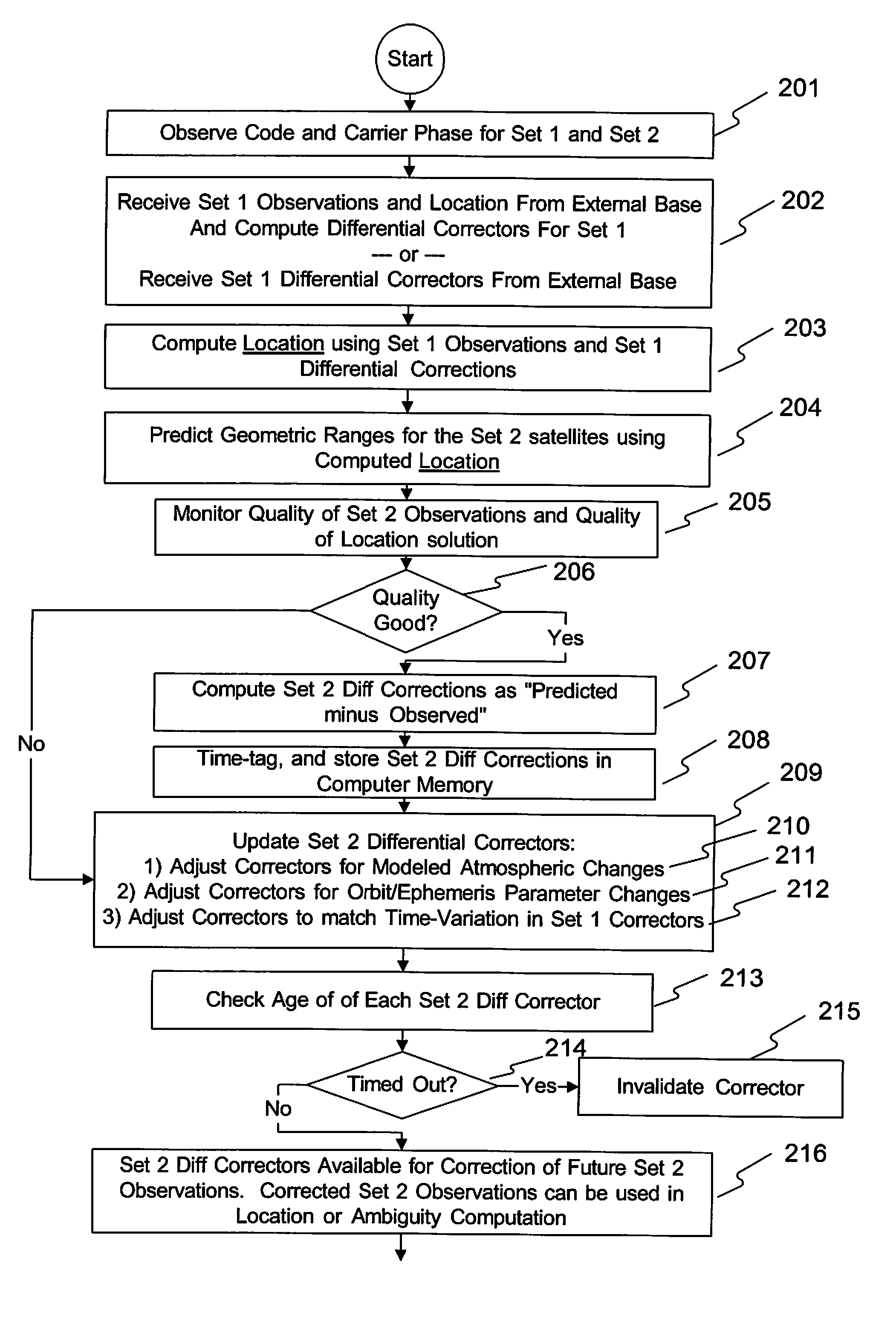
[0039]In the most common form, Differential GNSS (DGNSS) requires two GNSS receivers, a rover and a base receiver. The base is typically stationary at a known location and sends to a rover GNSS receiver phase (or pseudo-range) observations plus its known location, or in lieu of this, differential correctors or other differential enabling data. The rover takes the data from the base, and uses it to correct its own observations to increase their accuracy. The result is that the rover can provide a more accurate location using corrected observations, even to the centimeter level or less when carrier phase is used in an RTK solution.

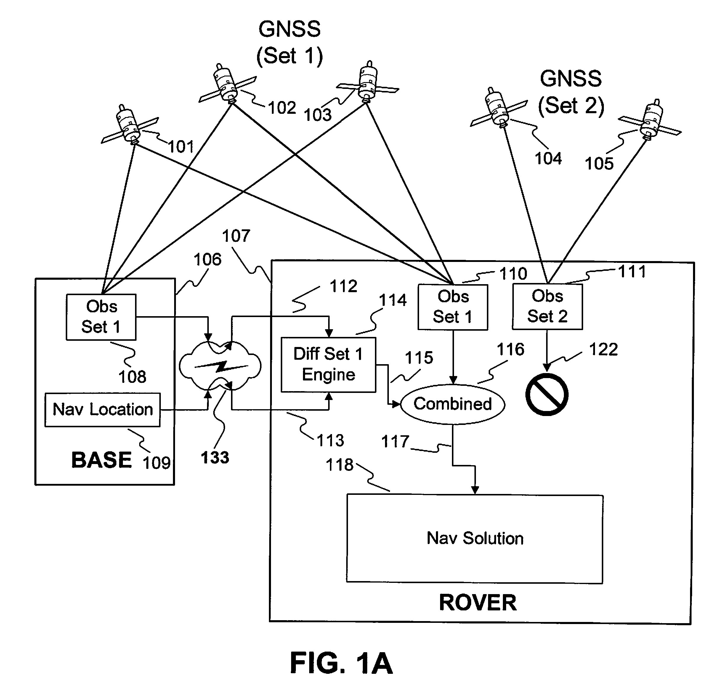
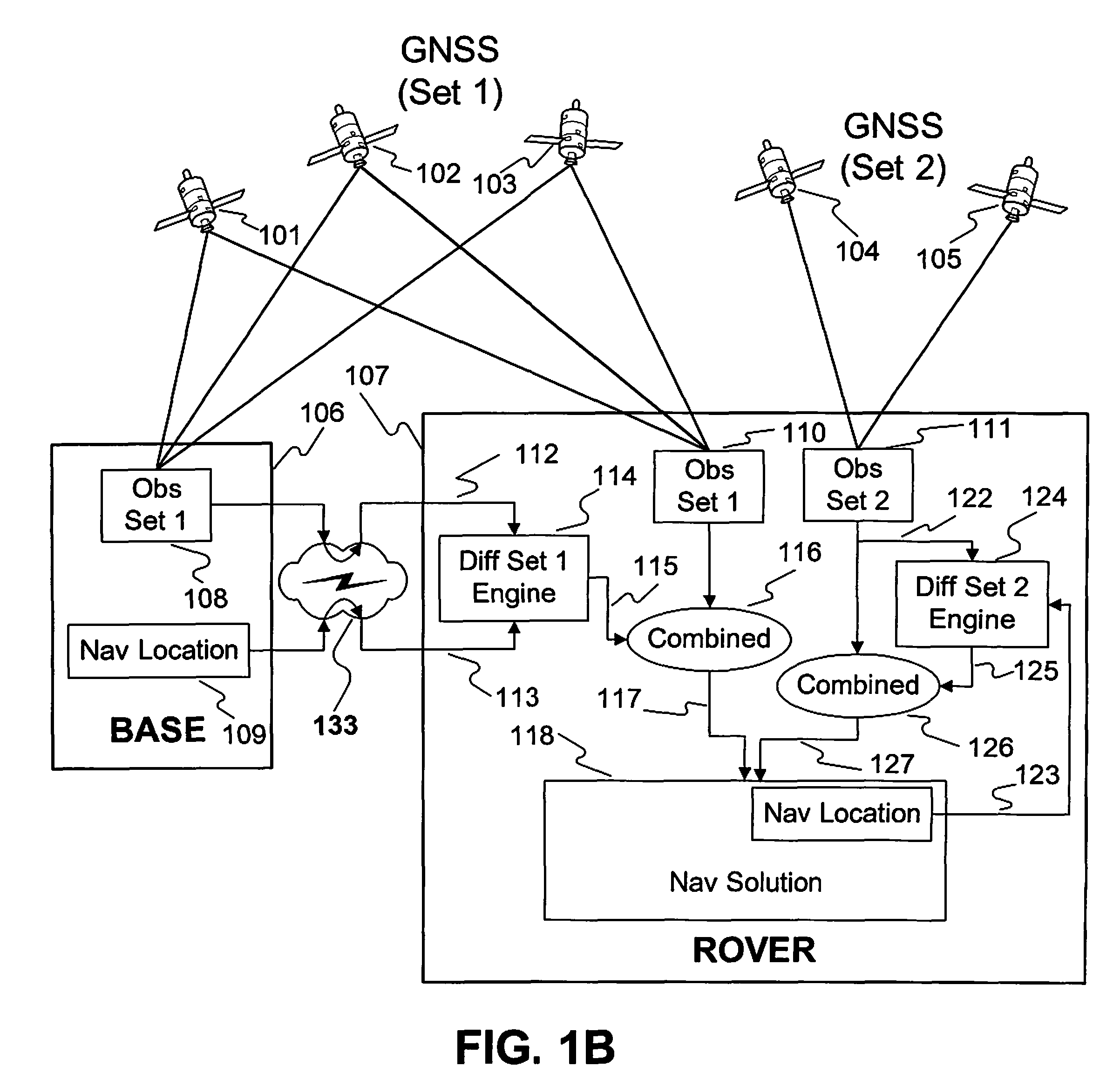
[0040]FIG. 1A shows the details of a typical DGNSS scenario with two sets of satellites involved. The sets could be from different GNSS constellations such as GPS and GLONASS, or simply one set that is observable to both receivers while the other set is observable only to the rover. As shown in FIG. 1A, satellite Set 1 is comprised of satellites 101, 102, an...


PUM


Abstract

In the invention, a rover receiver first utilizes data from a base Receiver, a DGNSS reference network, or other differential source to compute a differentially corrected location. Then, using this location and data observed only at the rover, the rover computes an internal set of differential corrections that are stored in computer memory, updated as necessary, and applied in future times to correct observations taken by the rover. The possibly mobile rover receiver, therefore, corrects its own observations with differential corrections computed from its own past observations; relying on external differential for the sole purpose of establishing a reference location, and this is unlike prior art.

Description

BACKGROUND OF THE INVENTION[0001]1. Field of the Invention[0002]The invention relates generally to methods for processing signals received from satellites within a Global Navigation Satellite System (GNSS) for example, Global Positioning System (GPS) receivers, and more particularly to a method for computing precise relative locations using differential GNSS / GPS techniques for all observations measured by a rover GNSS receiver, and not just those observations that are common to base and rover GNSS receivers.[0003]2. Description of the Related Art[0004]Evolution of GPS-only systems to a multi-constellation Global Navigation Satellite System (GNSS) employing GPS, GLONASS, Galileo, Compass and others has become a reality. This has a number of implications when it comes to differential-based positioning (commonly called DGPS or DGNSS), particularly when it comes to mixing legacy equipment with newer equipment, or when equipment is not compatible with respect to the types of GNSS signals...

Claims


Application Information

Patent Timeline
Patent Type & Authority Patents(United States)
IPC IPC(8): G01S19/41G01S19/07
CPCG01S19/33G01S19/41
Inventor WHITEHEAD, MICHAEL L.
Owner HEMISPHERE GNSS
Why Eureka
Try Eureka