
Dual-band antenna

Active Publication Date: 2012-05-08
INFINEON TECH AG
View PDF10 Cites 38 Cited by
  • Summary
  • Abstract
  • Description
  • Claims
  • Application Information

AI Technical Summary

Benefits of technology

[0012]In an embodiment, the shorted loop slot antenna is an ultra-high-frequency (UHF) band antenna. UHF band antennas have a high reading range and high data transmission rate.
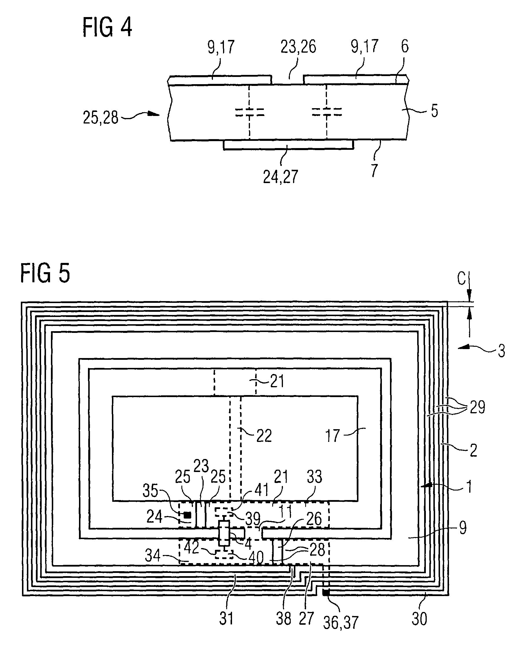
[0036]In an embodiment, a quality factor of the spiral antenna is determined by the conductor width of its conductor turns. A smaller conductor width leads to higher losses and to a lower quality factor. The wider bandwidth associated with a lower quality factor provides practical robustness to detuning effects.

Problems solved by technology

However, a challenge in designing dual-band antennas is to minimize the mutual interference between the individual antennas.

Method used


Image

  • Dual-band antenna
  • Dual-band antenna
  • Dual-band antenna

Examples


Embodiment Construction

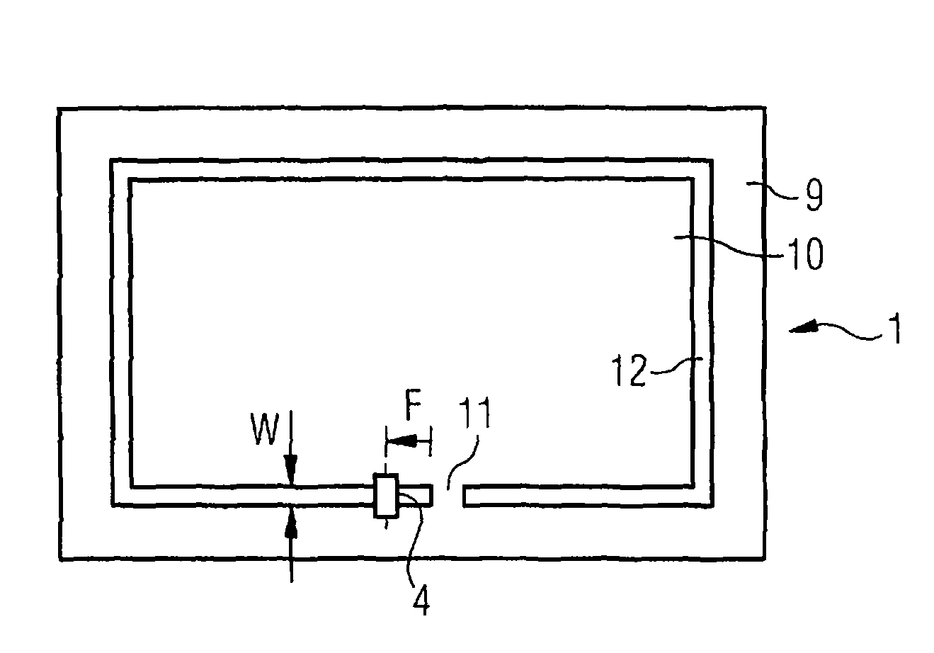
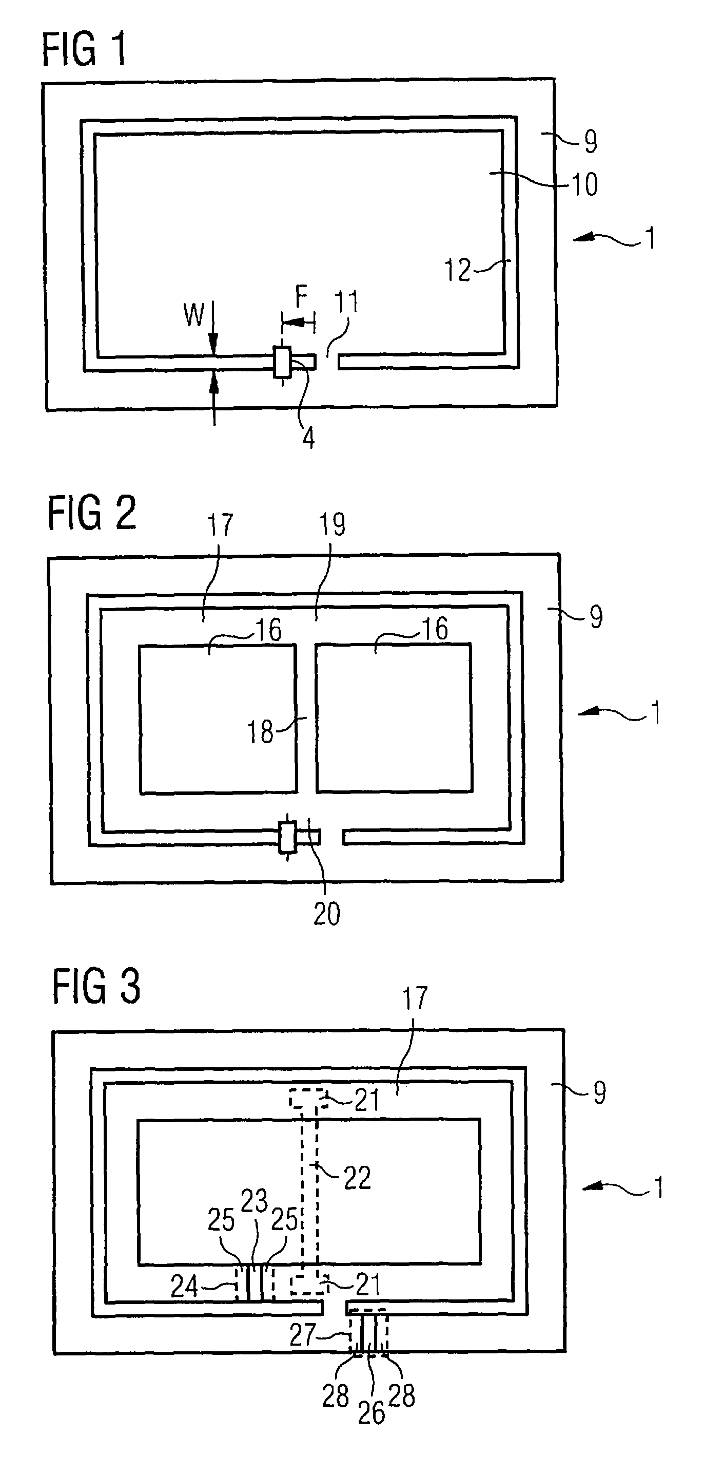
[0010]The invention provides a dual-band antenna comprising a shorted loop slot antenna and a spiral antenna. The antennas are combined to provide the advantages of each antenna type. Since the antennas have similar geometrical structures, the interference between the two antennas is minimal.

[0011]In an embodiment, the shorted loop slot antenna has a resonance frequency which is two orders of magnitude higher than a resonance frequency of the spiral antenna. The ratio of the frequencies of about 1 to 100 can be used to select electric paths by means of capacitors.

[0012]In an embodiment, the shorted loop slot antenna is an ultra-high-frequency (UHF) band antenna. UHF band antennas have a high reading range and high data transmission rate.

[0013]In an embodiment, the shorted loop slot antenna has a resonance frequency lying between 860 MHz and 960 MHz. The frequency range belongs to the industrial-scientific-medical (ISM) band which can be used for contactless data transmission, such a...


PUM


Abstract

Dual-band antenna including a shorted loop slot antenna and a spiral antenna.

Description

FIELD OF THE INVENTION[0001]The invention relates to a dual-band antenna.BACKGROUND OF THE INVENTION[0002]Dual-band antennas allow the use of frequencies in different bands. In contactless data storage media, such as radio frequency identification (RFID) tags, different frequency bands can be used to achieve optimum operation under different ambient conditions. Frequencies in the ultra-high-frequency (UHF) band of 300 MHz to 3 GHz allow a higher read range but are easily absorbed by liquids such as water. Frequencies in the high-frequency (HF) band between 3 MHz to 30 MHz are better able to penetrate water and other dielectric and lossy materials but have a shorter read range. The combination of a UHF band antenna with a HF band antenna allows to use the advantages of each frequency band. Further, a dual-band antenna allows more flexibility since it can operate in both frequency bands. However, a challenge in designing dual-band antennas is to minimize the mutual interference betwee...

Claims


Application Information

Patent Timeline
Patent Type & Authority Patents(United States)
IPC IPC(8): H01Q21/00H01Q5/10
CPCH01Q1/2225H01Q7/00H01Q9/27H01Q21/28
Inventor MAYER, LUKAS W.
Owner INFINEON TECH AG
Learn More