Method for the transmission and distribution of digital television signals

a technology of digital television and transmission method, applied in the field of transmission and distribution of digital television, can solve the problems of substantial price disparity at the consumer, hampered quest for high-definition television, etc., and achieve the effect of facilitating point-to-multipoint distribution and reducing the number of duplicate dedicated network assets

Active Publication Date: 2012-05-08
LEVEL 3 COMM LLC +1
View PDF32 Cites 9 Cited by
  • Summary
  • Abstract
  • Description
  • Claims
  • Application Information

AI Technical Summary

Benefits of technology

[0018]In another preferred embodiment TCP / IP packets are transmitted via dedicated routes which are determined and scheduled prior to the video transmission. Optionally, when finished programming is returned to the venue, a symmetric path can be provisioned for the returning program so that the need for duplicate dedicated network assets is reduced and to facilitate point-to-multipoint distribution.

Problems solved by technology

While the quest for high-definition television (“HDTV” or “HD”) has been hampered by the lack of a single standard, resistance by the broadcast industry to implementation, and a substantial price disparity at the consumer level, mandates from the Federal Communication Commission are forcing broadcasters and equipment manufacturers to transition from conventional analog transmission to digital television transmission.
Unfortunately, while the video signal may be digitized over some portion of its path, it starts out as an analog signal and is delivered as an analog signal.
Presently, satellite transponders are available which will carry DTV signals, however the issue of bandwidth is, at best, confusing.
Data rates vary widely from satellite-to-satellite and transponder sharing further complicates the issue.
Generally speaking, lossy compression techniques compress a signal in a manner designed to faithfully reproduce the content at the receiving end while not faithfully recreating the original digital signal.
The result is that these compression techniques, by necessity, add delay to the signal.
Simply providing more bandwidth to accommodate HDTV signals is hampered by any number of bottlenecks, such as: the data rate supported by the link between a venue and the fiber network, typically supplied by the local telephone company; the link between the fiber network and the receiving end; or even bandwidth limitations of various network elements.
As with satellite transmissions, for a given video format, compressing the video signal reduces quality and introduces delay.
Another issue with transmission over terrestrial carriers is reaching multiple receivers.
Still another issue in producing and distributing television programming is monitoring the broadcast video, including commercials, at the venue.
Even with analog programming, returning finished video to the production truck is problematic.
Yet another issue in the transmission of digital television signals is maintaining synchronization between video and audio portions of the signal.
Problems with synchronization arise when the audio signal takes a different path from that of the video signal and the delay in one of the paths is variable, or when the delay introduced through compression is variable.

Method used


Image

  • Method for the transmission and distribution of digital television signals
  • Method for the transmission and distribution of digital television signals
  • Method for the transmission and distribution of digital television signals

Examples


Embodiment Construction

[0030]Before explaining the present invention in detail, it is important to understand that the invention is not limited in its application to the details of the construction illustrated and the steps described herein. The invention is capable of other embodiments and of being practiced or carried out in a variety of ways. It is to be understood that the phraseology and terminology employed herein is for the purpose of description and not of limitation.

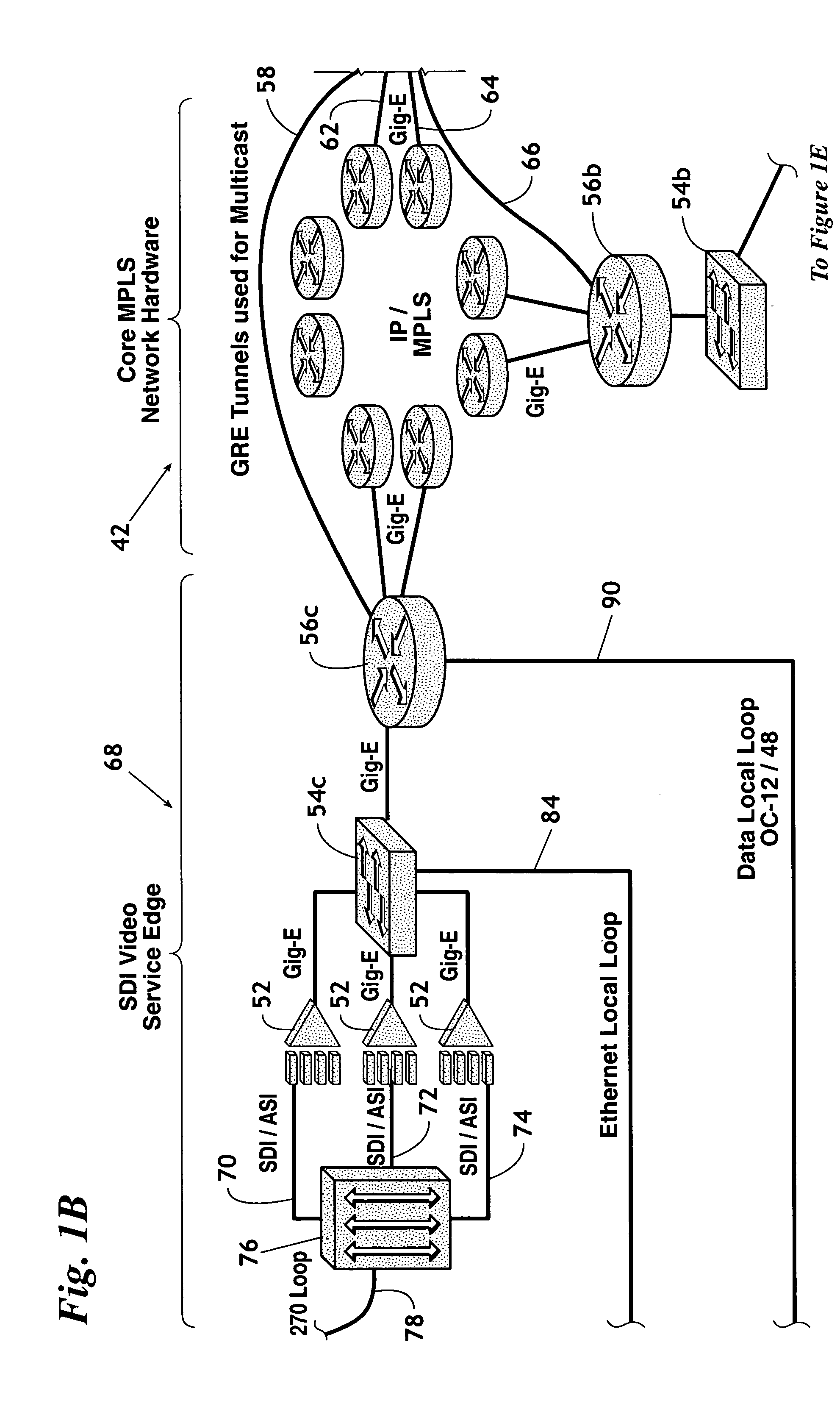
[0031]As will become apparent on reading the description of the preferred embodiments, while the inventive system is not limited to a single network architecture, in the preferred embodiments DTV information is transmitted, at least in part, over a multiprotocol label switching (“MPLS”) network. Such networks are well known in the art and, with the exception of specialty label ingress nodes and label egress nodes, as discussed further hereinbelow, the MPLS network of the present invention is conventional in nature.

[0032]In a MPLS netw...


PUM


Abstract

A system for the end-to-end delivery of digital television signals. In a preferred embodiment a digital television signal is: received from production equipment, typically in HD format at approximately 1.4 gigabits per second (Gbps); the received signal is transmitted to a venue point-of-presence; converted for transmission via a 270 Mbps local loop; transmitted to a fiber network point of presence / video service edge; packetized into TCP / IP packets in a video gateway; and routed to one or more destination addresses via the fiber network; received at one or more video service edge destinations; converted to a digital television format, typically SDI; and either transmitted via a second 270 Mbps local loop for delivery to a customer site and subsequent conversion to a 1.4 Gbps HD signal, or converted directly to a 1.4 Gbs HD signal at the receiving video service edge.

Description

BACKGROUND OF THE INVENTION[0001]1. Field of the Invention[0002]The present invention relates to a method for the transmission and distribution of digital television (DTV) signals. More particularly, but not by way of limitation, the present invention relates to a method for converting DTV signals to a format for transmission over a communication network, and transmitting the signal via the communication network to a remote location.[0003]2. Background of the Invention[0004]While the quest for high-definition television (“HDTV” or “HD”) has been hampered by the lack of a single standard, resistance by the broadcast industry to implementation, and a substantial price disparity at the consumer level, mandates from the Federal Communication Commission are forcing broadcasters and equipment manufacturers to transition from conventional analog transmission to digital television transmission. These mandates are certain to finally usher in the era of DTV, improving the quality of standard ...

Claims


Application Information

Patent Timeline
Patent Type & Authority Patents(United States)
IPC IPC(8): H04H20/71H04J3/00H04H20/28H04B7/212H04J1/00H04L12/56H04Q11/00H04J3/16H04J3/22H04J3/06H04L12/50H04M11/00H04M1/64
CPCH04N21/2343H04N21/2381H04N21/6405H04N21/64322H04N21/64707
Inventor BEAUDOIN, SCOTTJONES, SCOTTBRILLHART, SCOTTBROWN, MICHAELKORTE, RYAN
Owner LEVEL 3 COMM LLC
Why Eureka
Try Eureka