Range measurement apparatus and method using chaotic UWB wireless communication

a wireless communication and range measurement technology, applied in the field of range measurement apparatus and method based on chaotic ultra wide band wireless communication technology, can solve the problems of hardly controlling the frequency band, low detection performance, obscure transformation possibility of a circuit or a device, etc., and achieves the effect of increasing the detection performance of chaotic signals and easy control of chaotic signal bandwidth

Inactive Publication Date: 2012-05-08
ELECTRONICS & TELECOMM RES INST
View PDF53 Cites 1 Cited by
  • Summary
  • Abstract
  • Description
  • Claims
  • Application Information

AI Technical Summary

Benefits of technology

[0016]A range measurement apparatus and method of the present invention can easily control a chaotic signal bandwidth by improving a chaotic oscillator of a conventional chaotic UWB wireless communication system, increase a chaotic signal detection performance by improving a typical on / off keying method, and perform communication and measure a range by employing a range measurement function, which is not provided in conventional technologies.

Problems solved by technology

However, the transformation possibility of a circuit or a device has been obscure in the Chua's circuit.
However, the chaotic UWB wireless communication system can hardly control the frequency band of the chaotic signals, and it shows a low detection performance because it adopts a conventional on / off keying method.
However, no communication system having a range measurement function has been suggested in connection with the conventional chaotic UWB wireless communication technology.

Method used


Image

  • Range measurement apparatus and method using chaotic UWB wireless communication
  • Range measurement apparatus and method using chaotic UWB wireless communication
  • Range measurement apparatus and method using chaotic UWB wireless communication

Examples


Embodiment Construction

[0028]Other objects and aspects of the invention will become apparent from the following description of the embodiments with reference to the accompanying drawings, which is set forth hereinafter. Accordingly, those skilled in the art of the present invention can easily implement the technological concept of this invention. When it is considered that detailed description on a related art may obscure a point of the present invention, it will not be provided herein. Hereinafter, embodiments of the present invention will be described in detail with reference to the drawings.

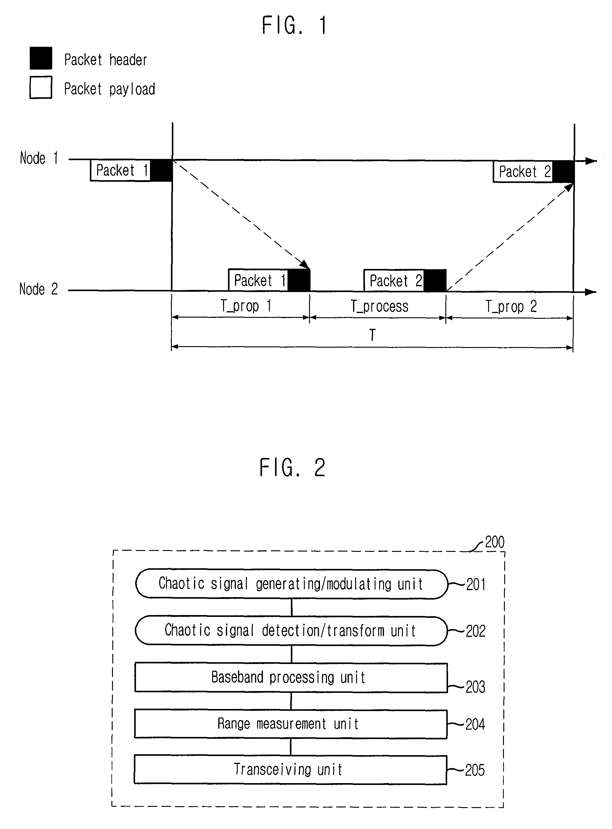
[0029]FIG. 2 is a block diagram showing a range measurement apparatus employing a chaotic UWB wireless communication technology in accordance with an embodiment of the present invention.

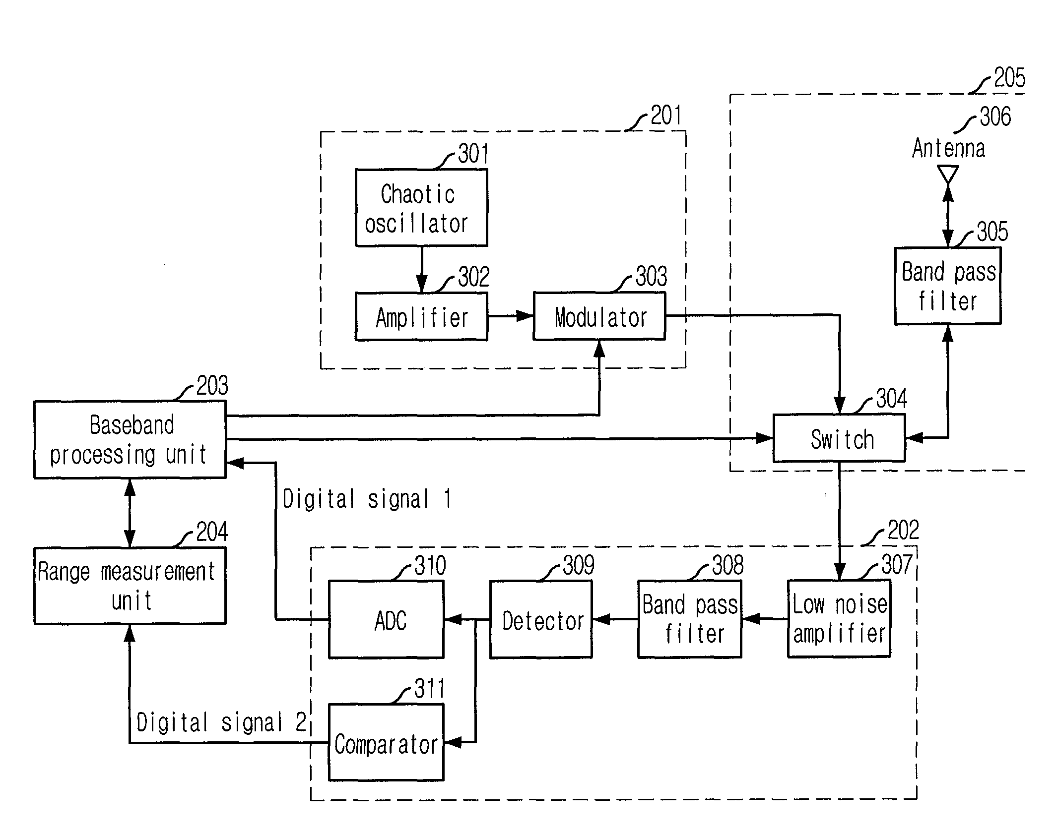
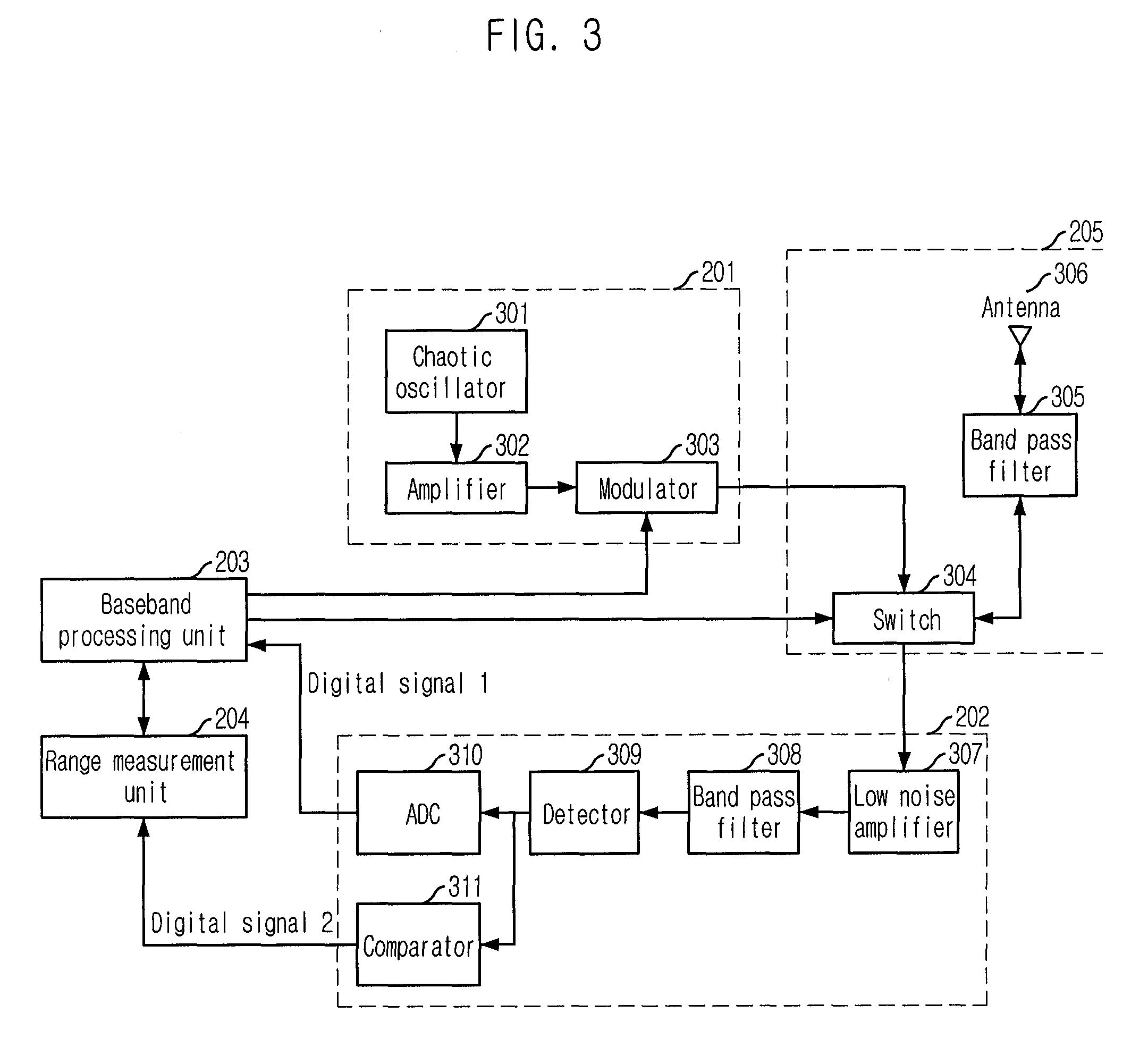
[0030]As shown in the drawing, the range measurement apparatus 200 measures a range as soon as it transmits / receives digital data by transmitting / receiving chaotic signals in the form of packets. The range measurement apparatus 200 i...


PUM


Abstract

An apparatus for measuring a range based on a chaotic ultra wideband (UWB) wireless communication technology is disclosed. The Apparatus includes a chaotic signal generating / modulating unit, a transceiving unit, a detecting unit, a transform unit, a comparison unit, and a range measurement unit. The transform unit converts the analog voltage signal from the detecting unit into digital signals based on a first sampling period. The comparison unit compares the analog voltage signal from the detecting unit with a predetermined threshold value and to output a comparison signal. The range measurement unit is configured to calculate a time point corresponding to a leading edge, which is a moment when initial data of a packet payload arrive, by using the digital signals based on the threshold value and by using the comparison signal, and to perform a range measurement calculation based on the time point corresponding to the leading edge.

Description

CROSS REFERENCE TO RELATED APPLICATION[0001]This application claims the priority of Korean Patent Application No. 10-2005-0119592, filed on Dec. 8, 2005 and the priority of Korean Patent Application No. 10-2006-0044690, filed on May 18, 2006 in the Korean Intellectual Property Office, the disclosure of which are incorporated herein in their entirety by reference. Further, this application is the National Phase application of International Application No. PCT / KR2006 / 001973, filed May 25, 2006, which designates the United States and was published in English. This application, in its entirety, is incorporated herein by reference.TECHNICAL FIELD[0002]The present invention relates to a chaotic Ultra Wide Band (UWB) wireless communication technology; and, more particularly, to a range measurement apparatus and method based on chaotic UWB wireless communication technology.BACKGROUND ART[0003]Among Ultra Wide Band (UWB) wireless communication technologies which have made a remarkable advanc...

Claims


Application Information

Patent Timeline
Patent Type & Authority Patents(United States)
IPC IPC(8): H04L29/06G01S19/15
CPCG01S13/0209G01S13/106G01S13/74G01S13/765H04L27/001
Inventor LEE, CHEOL-HYOKIM, JAE-YOUNG
Owner ELECTRONICS & TELECOMM RES INST
Why Eureka
Try Eureka