Method and apparatus for connecting AC powered switches, current sensors and control devices via two way IR, fiber optic and light guide cables

a technology of ac powered switches and current sensors, applied in electrical devices, transmission systems, instruments, etc., can solve the problems of inability to positively verify the on-off power status without, high cost of ac electrical customizing, and inability to reach the signal of other rooms within the residence, etc., to achieve the effect of low cost and simple attachmen

Active Publication Date: 2012-05-08
ELBEX VIDEO LTD
View PDF94 Cites 95 Cited by
  • Summary
  • Abstract
  • Description
  • Claims
  • Application Information

AI Technical Summary

Benefits of technology

[0027]The apparatus for remotely operating AC powered appliances and other objects of the present invention are attained by connecting a light guide or fiber optic cable between the IR AC switching device and a wired low voltage IR control device for communicating one or two way IR signals including commands to operate the electrical appliances and the IR AC switching device, and command confirmation including the AC current statuses of the connected electrical appliances, thereby generating on-off status signals from the appliances, in response to the received operational command or in response to an inquiry command (a request for status data) on the basis of the current sensor output, thereby providing error free remote controlling of the electrical home appliances.
[0030]The method of adding packaged IR AC switching devices and / or the IR current sensor devices to an existing standard electrical switches and outlets instead of replacing them, introduces several major advantages; one is the lowering of the overall cost of the switches and outlets, because standard low cost, mass produced switches and outlets can be used. The second advantage is that the “IR AC devices” provide dual operation, manual operation via the commonly used switches and outlets on one hand and remote operation, in parallel with manual operation, via the IR AC switching devices. These advantages are the other objects of present invention, attained in total harmony and with no conflict between the manual and remote switching operation as described in the pending US applications.
[0036]For this reason another object of the present invention is the use of dual triac circuit, termed also SPDT triac for its SPDT switching, because triac can well absorb 10 times surge current. Moreover the use of triac enables to limit the power fed to the appliance to, for example, 95% of the rated voltage, enabling the use of the residual 5% AC voltage to power the CPU for controlling the triacs including the IR receiver and transmitter, thereby providing a low cost and simple attachment of a light guide, and the use of the existing electrical wiring as is, by connecting the IR AC power device to the live AC wire and the load wire, requiring no neutral wire and no changes in the standard wiring of the electrical system.

Problems solved by technology

Most of the remote control devices, including IR or wireless remote control devices use the same power key to switch the appliance on and off, therefore without the operating person's self verification on site, with most of currently available remote control devices it is impossible to positively verify the on-off power status without being at the appliance site.
The problem such system represents is the cost for customizing of the AC electrical wiring, which are expensive and require expertise to configure, install and setup.
Moreover, many of the known AC wiring regulations forbid the connecting of the AC wires and low voltage wired control systems inside the same electrical box and / or the connections of AC power wires and low voltage control wires to the same relay, remote switch and / or electrical power devices such as light dimmers.
The problem however for such remote controlling is the need for a verified on-off status of the appliances being operated and / or the availability of a status report covering all the remotely controlled appliances of a given house, office, apartment or a building.
But because of the electrical safety regulations in many countries including the US, it is forbidden to connect a low voltage communication line to an AC power switch or a dimmer inside the same electrical box.
The wireless and IR remote control devices can be used for the two way communications, however for the IR remote control a line of sight is necessary, and in the case of wireless, the signal may not reach devices in other rooms within the residence.
This presents an uncertainty in commanding the switching on-off and the verifying of the appliance status and a solid verifiable communication via inter-connections between a low voltage powered control device and an AC power switch or a dimmer is needed.

Method used


Image

  • Method and apparatus for connecting AC powered switches, current sensors and control devices via two way IR, fiber optic and light guide cables
  • Method and apparatus for connecting AC powered switches, current sensors and control devices via two way IR, fiber optic and light guide cables
  • Method and apparatus for connecting AC powered switches, current sensors and control devices via two way IR, fiber optic and light guide cables

Examples


Embodiment Construction

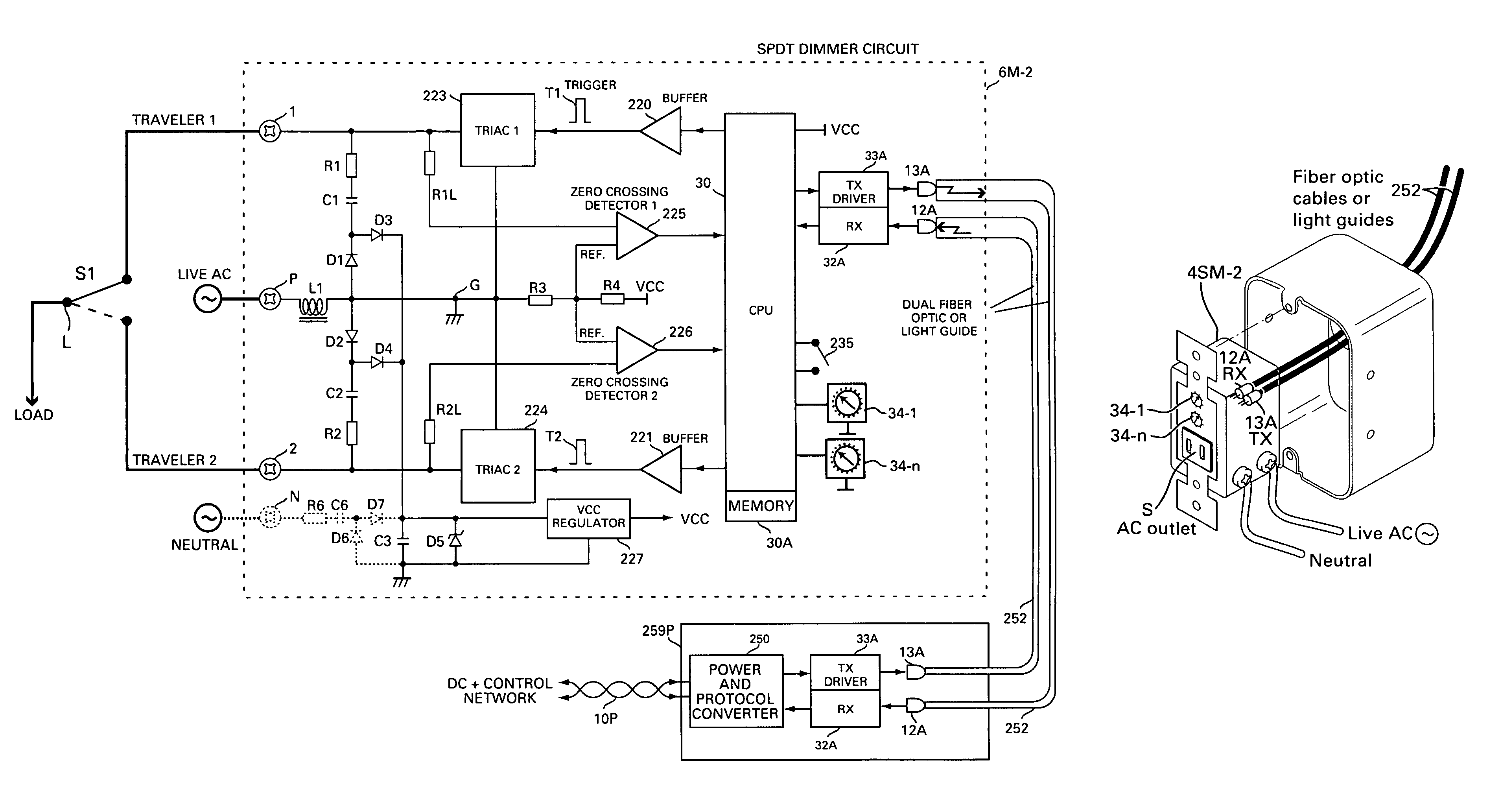
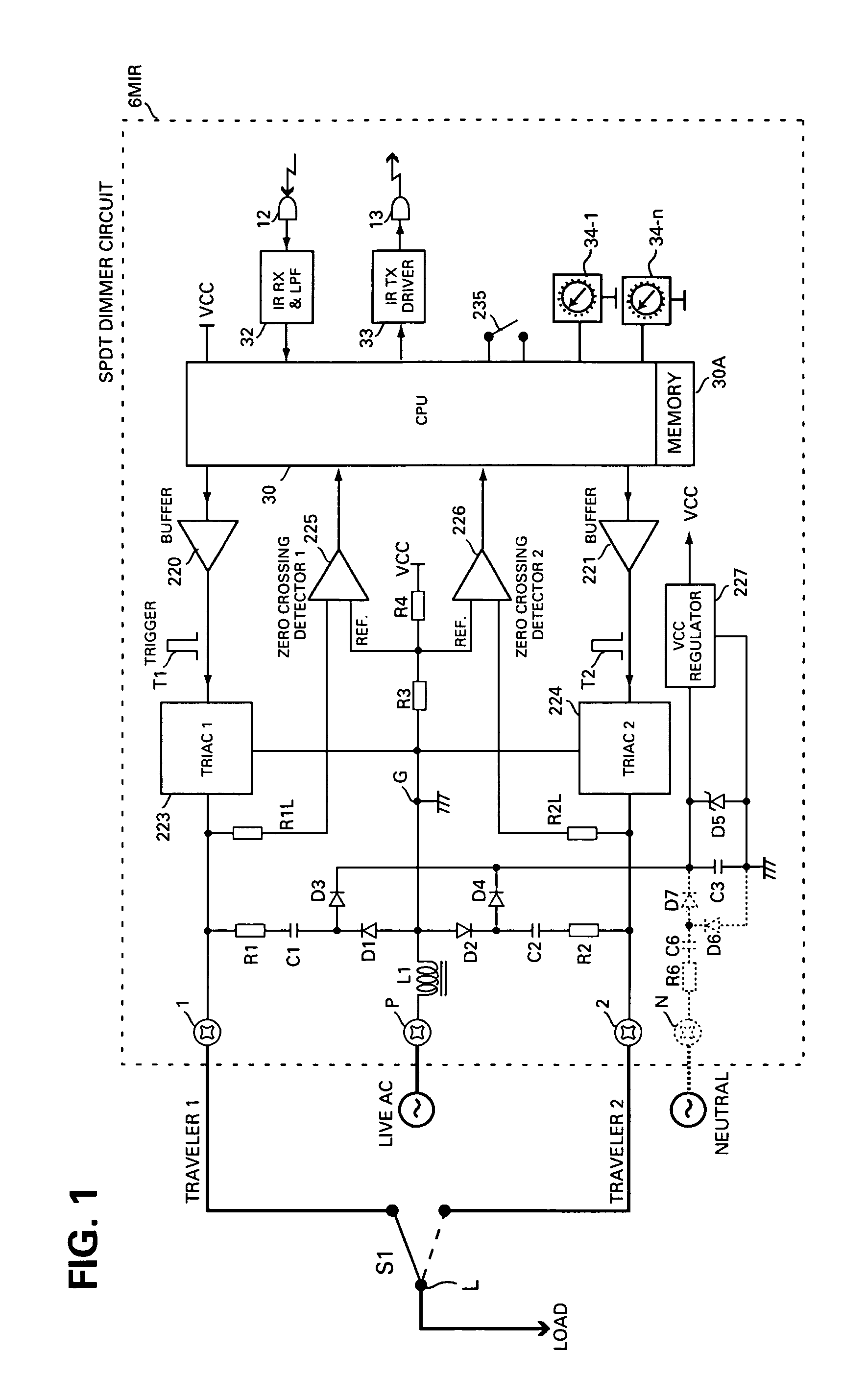
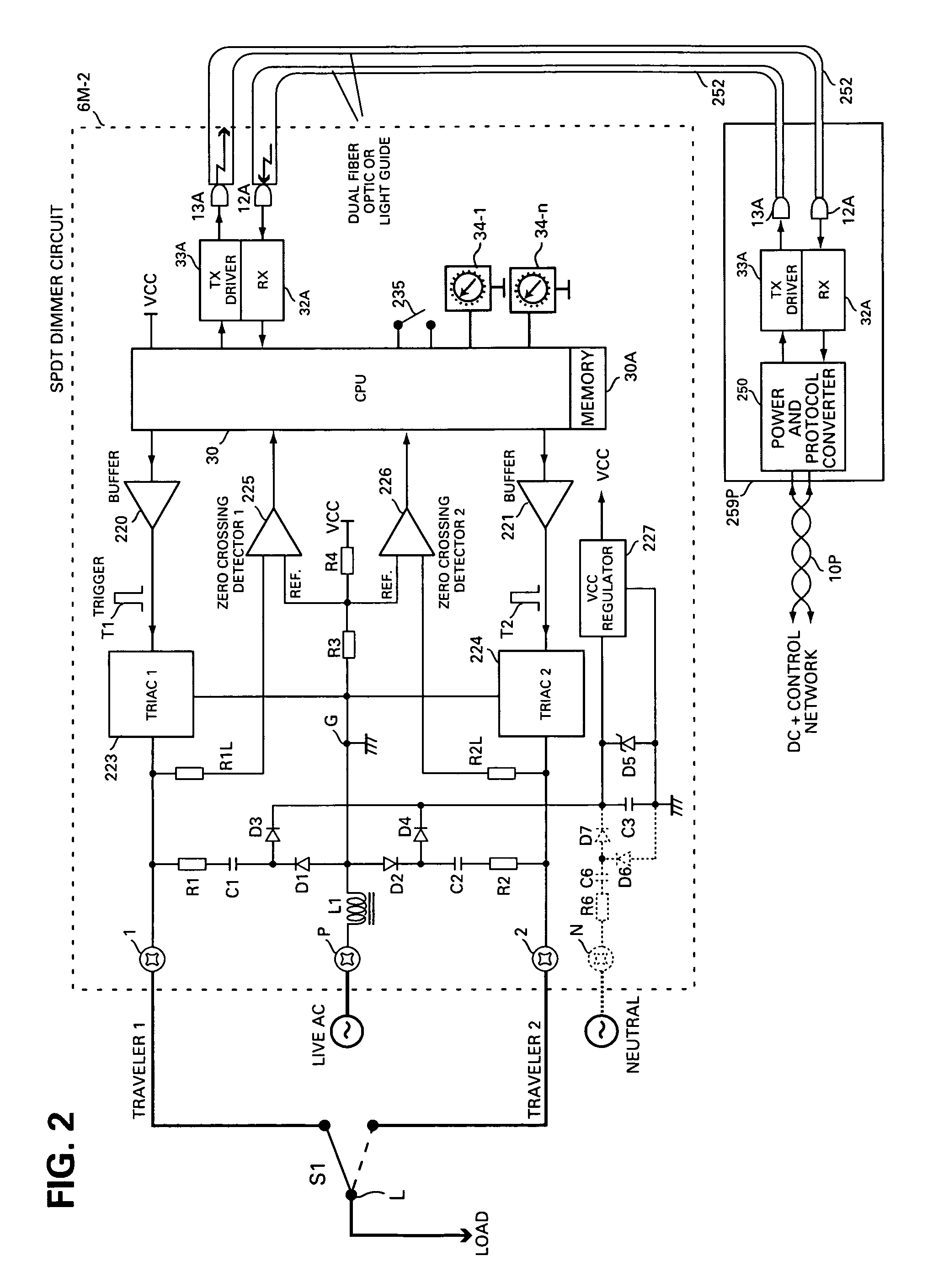
[0054]Shown in FIG. 4A is a well known basic on-off switching circuit, for switching AC appliances, including appliances such as light fixtures, from two independent switches S1 and S2. The standard on-off switches S1 and S2 are known as a single pole-dual throw (SPDT) switches that includes lever actuated spring contacts for making or breaking the electric circuit carrying AC current to the appliance. Remotely operated switch used for home automation disclosed in the pending US applications is in fact an SPDT relay contacts for making or breaking the AC current fed to an AC appliance, such as the relay assembly 6 of FIGS. 4B and 4D.

[0055]The basic switching circuit of FIG. 4A connects the two switches via two traveler lines and the shown circuit of the SPDT relay assembly 6, disclosed in the pending US applications, is connected via dual traveler lines to a commonly used SPDT AC switch 1B illustrated in a corresponding circuit shown in FIG. 4B for providing two independent on-off s...


PUM


Abstract

A method for connecting an AC powered device, which has an optical receiver, with a control circuit, which has an optical transmitter, using at least on optical medium cable includes the steps of terminating the cable at both of its ends, introducing the processed cable between the receiver and transmitter, attaching and securing one end of the processed cable to the transmitter and the other end of the processed cable to the receiver, and propagating a one way optical signal including control commands from the control circuit to the powered device.

Description

BACKGROUND OF THE INVENTION[0001]1. Field of the Invention[0002]This invention is related to home automation control including video interphone system for remotely operating AC power switches and electrical devices and appliances via two way IR remote control, fiber optic and light guide cables.[0003]2. Description of the Prior Art[0004]Wired or wireless remote control devices including InfraRed (IR) or RF transmitter for remotely operating AC powered electrical appliances such as television receivers, home heaters, air conditioners, motorized curtains, lighting and other electrical appliances in homes, apartments, offices and buildings in general do switch the appliances on-off, with the person operating the remote control device verifying the on or off status of the operated device by visual means, such as the TV is on, or the lights are off, or the aircondition unit is activated or not, by being at the site of the operated appliance. Most of the remote control devices, including ...

Claims


Application Information

Patent Timeline
Patent Type & Authority Patents(United States)
IPC IPC(8): H04B10/00
CPCG08C23/06H04M19/00H04Q1/28H04M11/04
Inventor ELBERBAUM, DAVID
Owner ELBEX VIDEO LTD
Why Eureka
Try Eureka