Artificial airway apparatus

a technology of airway apparatus and airway tube, which is applied in the direction of breathing mask, inhalator, breathing protection, etc., can solve the problems of high sealing efficiency, accumulation of such secretions, and pneumonia, and achieve the effect of high sealing efficiency

Active Publication Date: 2012-05-15
INDIAN OCEAN MEDICAL INC
View PDF24 Cites 6 Cited by
  • Summary
  • Abstract
  • Description
  • Claims
  • Application Information

AI Technical Summary

Benefits of technology

[0009]Although the provision of a balloon or cuff, or some such expedient solves the problem of gas escape, it can itself cause problems. One such problem is caused by the high sealing efficiency that can be achieved by some balloons and cuffs in the trachea. When the device is properly in place in a patient, the tube extends into the trachea with the balloon or cuff forming a seal around the tube, between the tracheal wall and the tube. The balloon or cuff defines, in effect, upper and lower, or lung side and mouth side sections of the airway. If the balloon or cuff in the trachea is fully effective in preventing passage of fluid, in some cases liquids such as the patient's own secretions can accumulate and pool above, or on the mouth side of the balloon or cuff. The accumulation of such secretions is a problem because it can form a reservoir for the growth of microorganisms such as bacteria. The growth and proliferation of bacteria in the trachea is itself extremely undesirable, and more so if on removal of the tube they pass into the lungs, which can result in the development of pneumonia. It is an object of the invention to seek to mitigate problems such as this.

Problems solved by technology

Although the provision of a balloon or cuff, or some such expedient solves the problem of gas escape, it can itself cause problems.
One such problem is caused by the high sealing efficiency that can be achieved by some balloons and cuffs in the trachea.
The accumulation of such secretions is a problem because it can form a reservoir for the growth of microorganisms such as bacteria.
The growth and proliferation of bacteria in the trachea is itself extremely undesirable, and more so if on removal of the tube they pass into the lungs, which can result in the development of pneumonia.
It is envisaged that in some situations, the application of suction might cause blockage of a port if that port is in close proximity to the lining of the trachea.

Method used


Image

  • Artificial airway apparatus
  • Artificial airway apparatus
  • Artificial airway apparatus

Examples


Embodiment Construction

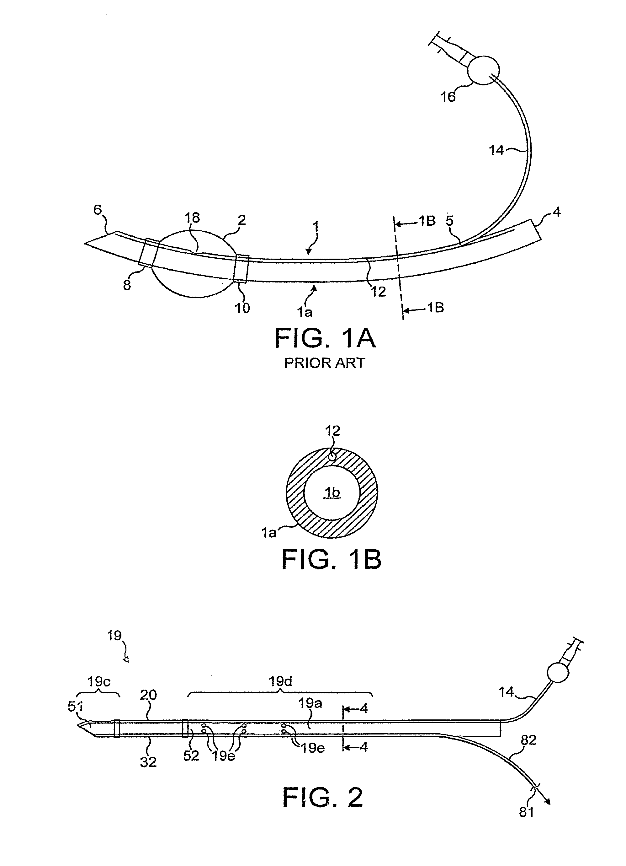
[0039]Referring to the drawings, FIG. 1A shows a prior art endotracheal tube (ETT) 1. FIG. 1B shows a magnified sectional view of ETT 1 taken along line 1B-1B as shown in FIG. 1A. ETT 1 includes a semi-rigid hollow tube 1a, which extends from a proximal end 4 to a distal end 6. Tube 1a is made from poly-vinyl-chloride (PVC). ETT 1 further includes an inflatable balloon, or cuff, 2 mounted near distal end 6. Balloon 2 is sealed to hollow tube 1a at locations 8 and 10 to form an airtight space within the balloon. ETT 1 further includes a central airway lumen 1b, which extends from the proximal end 4 to the distal end 6 of hollow tube 1a. Hollow tube 1a further defines a small inflation lumen 12, which extends through the wall of hollow tube 1a.

[0040]Inflation lumen 12 provides an opening 18 near its distal end within the interior volume of the balloon 2. At location 5, near the proximal end of hollow tube 1a, the inflation lumen 12 is connected to an inflation line, or tube, 14. An a...


PUM


Abstract

The invention relates to apparatus (19) for use in establishing an artificial airway in a patient, the apparatus comprising a tube (19a) for introduction into the patient's trachea for passage of gases to and from the patient's lungs, an inflatable seal (20) disposed upon the tube (19a) to provide, on inflation, a seal between the tube and the trachea of the patient, the seal (20) thereby defining a lung-side portion (19c) of the apparatus and a mouth-side portion (19d) of the apparatus, the apparatus further having the ability to facilitate removal of fluid from at or adjacent the said mouth-side portion (19d) of the apparatus (19).

Description

CROSS-REFERENCE TO RELATED APPLICATIONS[0001]This application is a national stage application under 35 U.S.C. §371 of International Patent Appln. PCT / EP2005 / 005754, designating the United States and filed on May 25, 2005, which is incorporated herein by reference.STATEMENT REGARDING FEDERALLY SPONSORED RESEARCH OR DEVELOPMENT[0002]Not Applicable.THE NAMES OF THE PARTIES TO A JOINT RESEARCH AGREEMENT[0003]Not Applicable.INCORPORATION-BY-REFERENCE OF MATERIAL SUBMITTED ON A COMPACT DISC[0004]Not Applicable.BACKGROUND OF THE INVENTION[0005]1. Field of the Invention[0006]The present invention relates to artificial airway apparatus for use in establishing an artificial airway in a patient, and in particular to an artificial airway device which includes a balloon or similar device for sealing the trachea against unwanted escape of gases when the device is in place.[0007]2. Description of Related Art Including Information Disclosed Under 37 C.F.R. 1.97 and 1.98[0008]Artificial airway devic...

Claims


Application Information

Patent Timeline
Patent Type & Authority Patents(United States)
IPC IPC(8): A61M16/00A61M16/04
CPCA61M16/04A61M16/0409A61M16/0431A61M16/0479A61M16/0434A61M16/0488A61M16/0443A61M16/0486
Inventor YOUNG, PETER J.
Owner INDIAN OCEAN MEDICAL INC
Why Eureka
Try Eureka