Accoustic attenuation device for an intake line of a combustion engine and intake line incorporating same

a technology of exhaust gas attenuation device and combustion engine, which is applied in the direction of sound producing device, air intake for fuel, air cleaner for fuel, etc., can solve the problems of reducing the acoustic performance of the device for a given length of time, affecting the ability of the device to withstand pressure and the acoustic performance of the device, and reducing the working volume. , the method of manufacturing the device according to the invention can be simplified, and the effect o

Active Publication Date: 2012-05-15
HUTCHINSON SA
View PDF19 Cites 18 Cited by
  • Summary
  • Abstract
  • Description
  • Claims
  • Application Information

AI Technical Summary

Benefits of technology

[0012]It will be noted that the or each condensate discharge orifice provided in a Helmholtz resonator according to the invention notably makes it possible to avoid the buildup, in the or each resonator, of hot oil and dust carried along by the fluid coming from the engine and condensing out upon contact with the walls, which buildup over the long term forms a pasty solid deposit that reduces the working volume of the corresponding chamber and thus disrupts the acoustic attenuation. In other words, this gravity discharge of condensate that the attenuation device according to the invention affords thus allows the acoustic performance of the or each Helmholtz resonator that it comprises to be a lasting performance.
[0014]It will also be noted that this forming of the cover as one piece with the transverse and longitudinal partitions of the or each resonance chamber overcomes the aforementioned disadvantage of the prior art relating to the welding together of plastic components, thus avoiding the device becoming contaminated during the welding operation and making this device perfectly airtight in the region of the cover. In addition, this one-piece structure means that the method of manufacture of the device according to the invention can be simplified thus reducing its cost of production.
[0015]According to another feature of the invention, the housing and the cover may be formed as one piece with a radially external duct of the conduit structure thereby forming a one-piece assembly made of a plastic preferably by injection molding or blow molding, at least one anti-creep metal ring which is provided with said or each passage opening and with said or each discharge orifice being able to be inserted against the radially internal face of this duct to allow it to withstand high operating temperatures, such that the fluid flowing along the inside of the or each ring communicates directly with the or each chamber opposite.
[0019]It will be noted that the attenuation device according to the invention does in particular make it possible to generate reduced pressure drops for the fluid flowing therein, and this plays a part in improving engine performance by comparison with the known attenuation devices with two annular resonance chambers which generate higher pressure drops.
[0025]It will be noted that the attenuation device according to the invention may thus advantageously comprise a high number of Helmholtz resonators for a relatively small size, notably by comparison with the known attenuation devices with annular resonance chambers, while at the same time being adaptable to suit any surroundings so that it can be mounted in an intake line.

Problems solved by technology

One major disadvantage of the known attenuation devices of the type having annular resonance chambers lies in their relatively large size and in the low number of resonance chambers formed, which is generally limited to two, thus penalizing the acoustic performance for a given length of device.
As for known attenuation devices of the Helmholtz resonator type, these have the notable disadvantage of providing, over a greater or shorter length of time, an acoustic attenuation that is unsatisfactory both in respect of the hissing noises generated by the turbocharged engine (manifesting themselves in the form of pressure pulses in the low frequencies typically ranging from 1300 to 2000 Hz approximately) and in terms of the whistling noises also generated by this engine (high frequencies above around 2500 Hz).
These Helmholtz resonator devices also sometimes have the disadvantage of requiring several plastic components to be welded together, for example of requiring a cover to be welded to the wall of the resonance chamber(s), to the detriment of the method of manufacture of the device in terms of cleanliness, ease of implementation and cost, and also being potentially detrimental to the ability of the device to withstand pressure and the acoustic performance of the device, particularly on account of difficulties with controlling the geometric tolerances and / or the deformations of the welded plastic under the effect of temperature, this potentially giving rise to air leaks.

Method used


Image

  • Accoustic attenuation device for an intake line of a combustion engine and intake line incorporating same
  • Accoustic attenuation device for an intake line of a combustion engine and intake line incorporating same
  • Accoustic attenuation device for an intake line of a combustion engine and intake line incorporating same

Examples


Embodiment Construction

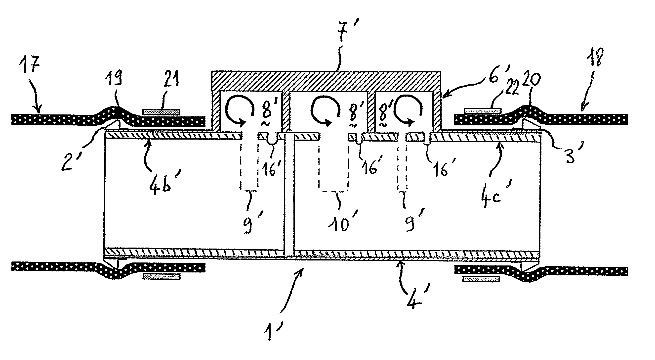
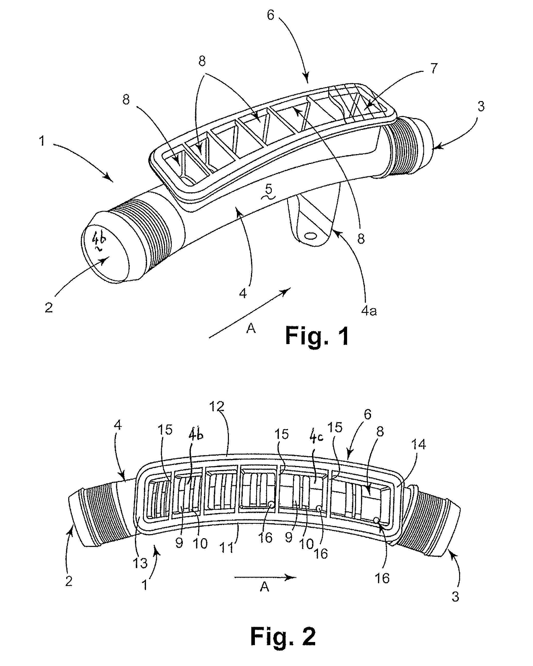
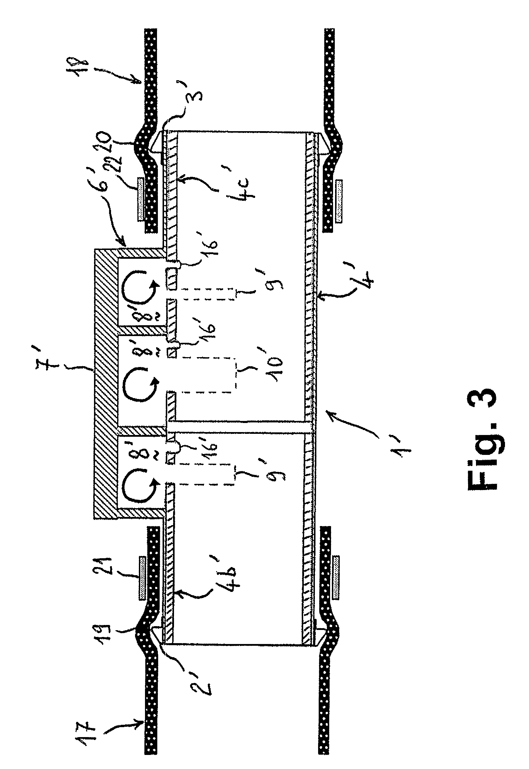
[0033]The acoustic attenuation device 1 illustrated in FIGS. 1 and 2 is intended to be incorporated into an air intake line of a turbocharged motor vehicle engine, via its two respective connecting ends 2 and 3 for the inlet and outlet of pressurized air. This device 1 essentially comprises:[0034]a one-piece plastic assembly, for example blow molded or injection molded, comprising a plastic conduit or duct 4 which has a tubular wall 5 of cylindrical overall shape ending in these two connecting ends 2 and 3 and which is provided with an attachment mount 4a, this conduit being extended as a single piece by a housing 6 which is closed by a cover 7 and contains several resonance chambers 8—six in this example—forming that same number of Helmholtz resonators following on from one another in the axial direction A of the conduit 4, and[0035]two metal anti-creep rings 4b and 4c which are forcibly inserted against the radially internal face of the conduit 4 being positioned therein coaxially...


PUM

PropertyMeasurementUnit
frequenciesaaaaaaaaaa
frequencyaaaaaaaaaa

Abstract

The present invention relates to an acoustic attenuation device for an intake line of an internal combustion engine and to an intake line such as this incorporating same. An acoustic attenuation device according to the invention is intended to have a flow of pressurized gaseous fluid passing through it and comprises:a conduit structure which has a tubular wall ending in two ends, these respectively being the fluid inlet and fluid outlet ends, which are able to be incorporated into the intake line, andat least one resonance chamber which is arranged on the outside of this structure and which communicates therewith via at least one opening formed in said wall, the or each chamber being axially delimited by two transverse partitions. According to the invention, the or each chamber further comprises at least one gravity discharge orifice for discharging condensate which is formed in said wall in the vicinity of one of the transverse partitions, the or each chamber being delimited by two longitudinal walls which are joined together by these transverse partitions thereby forming a housing which is closed by a cover formed as one piece with this housing.

Description

FIELD OF THE INVENTION[0001]The present invention relates to an acoustic attenuation device for an intake line of an internal combustion engine such as a turbocharged engine for a motor vehicle and to an intake line such as this incorporating same. The invention applies to such a resonant chamber(s) attenuation device of the Helmholtz type.BACKGROUND OF THE INVENTION[0002]In the known way, acoustic attenuation devices for turbocharged motor vehicle engine intake lines comprise a tract through which pressurized air laden with oil is intended to travel and the air inlet and outlet ends of which are incorporated into this intake line. There are essentially two distinct types of device such as this, these including:[0003]those with a radially external tubular casing to the end portions of which a radially internal tract structure is secured to form two annular resonance chambers with two respective widenings of the casing, for example like that described in document DE-A1-199 56 172, an...

Claims


Application Information

Patent Timeline
Patent Type & Authority Patents(United States)
IPC IPC(8): F01N1/02
CPCF02M35/10321F16L55/02781F16L55/033F02M35/1216F02M35/1261F02M35/1266F02M35/1283F02B37/00F02M35/022F02M35/08
Inventor CALISKAN, ALPER
Owner HUTCHINSON SA
Why Eureka
Try Eureka