Stator for dynamoelectric machine and method of manufacturing same

a technology of dynamoelectric machines and stators, which is applied in the direction of dynamo-electric components, synchronous machines, windings, etc., can solve the problems of failing to effectively cool the axial end face of the other coil end is uneven in the extending direction of the connecting portion, and the coolant cannot flow smoothly along the axial end face of the other coil end, so as to achieve the same cooling effect and secure high cooling performance of the stator

Active Publication Date: 2012-05-15
DENSO CORP
View PDF9 Cites 2 Cited by
  • Summary
  • Abstract
  • Description
  • Claims
  • Application Information

AI Technical Summary

Benefits of technology

[0014]With the above configuration, when a coolant is supplied to cool the stator, the flow path of the coolant provided on the axial end face of the stator coil on one side of the stator core is identical to that provided on the axial end face of the stator coil on the other side of the stator core. As a result, it is possible to achieve the same cooling effect on both the axial end faces of the stator coil, thereby making it possible to secure high cooling performance of the stator.

Problems solved by technology

Since each of the connecting portions of the electric wires extends to form the shape of a triangle, the axial end faces of the coil ends become uneven in the extending directions of the connecting portions.
However, with the stator coil formed with the flat band-shaped electric wire assembly manufactured by the conventional method, the flow of the coolant passing the axial end face of one of the coil ends is different from that passing the axial end face of the other coil end.
Consequently, the coolant cannot smoothly flow along the axial end face of the other coil end, thereby failing to effectively cool the other coil end.

Method used


Image

  • Stator for dynamoelectric machine and method of manufacturing same
  • Stator for dynamoelectric machine and method of manufacturing same
  • Stator for dynamoelectric machine and method of manufacturing same

Examples


first embodiment

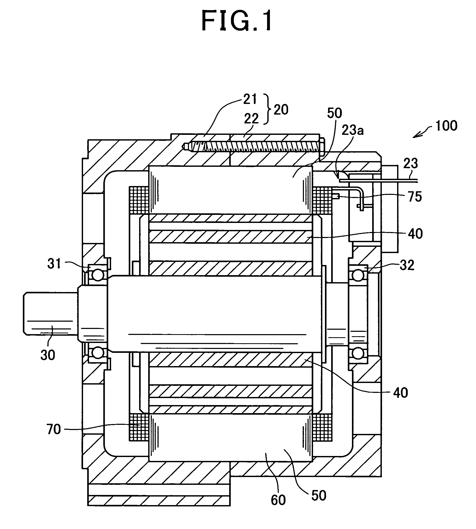
[0045]FIG. 1 shows the overall configuration of a dynamoelectric machine 100 which includes a stator 50 according to the first embodiment of the invention.

[0046]The dynamoelectric machine 100 is configured to function as either an electric generator or an electric motor in a motor vehicle, such as an electric vehicle or a hybrid vehicle.

[0047]As shown in FIG. 1, the dynamoelectric machine 100 further includes a housing 20 and a rotor 40 in addition to the stator 50. The housing 20 is composed of a pair of cup-shaped housing pieces 21 and 22 which are jointed together at the open ends thereof. The housing 20 has a pair of bearings 31 and 32 mounted therein, via which a rotating shaft 30 is rotatably supported by the housing 20. The rotor 40 is received in the housing 20 and fixed on the rotating shaft 30. The stator 50 is fixed in the housing 20 so as to surround the radially outer periphery of the rotor 40.

[0048]The rotor 40 includes a permanent magnet that is provided on a radially...

second embodiment

[0088]This embodiment illustrates a method of manufacturing a stator for the dynamoelectric machine 100, which is different from the method according to the previous embodiment.

[0089]As in the previous embodiment, the method according to the present embodiment also includes an electric wire-shaping step, an electric wire assembly-forming step, a stator coil-forming step, and a stator-assembling step.

1. Electric Wire-Shaping Step

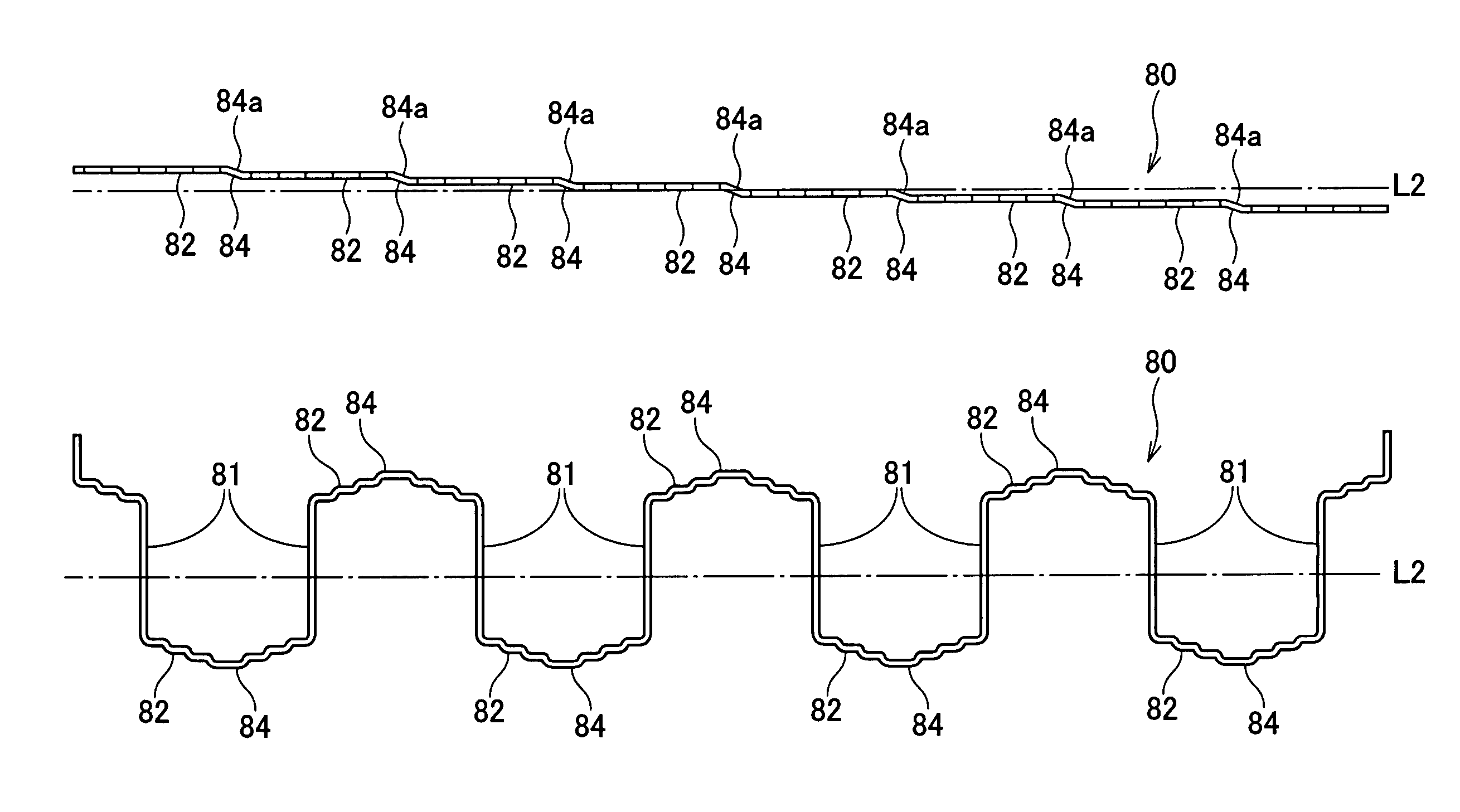
[0090]In this step, a total of 48 straight electric wires are shaped, using a shaping machine (not shown), to form four groups of wave-shaped electric wires 80 as shown in FIGS. 5A-5C. Each of the four groups includes twelve electric wires 80. All of the electric wires 80 in the same group have the same length. However, the electric wires 80 in different groups have different lengths.

2. Electric Wire Assembly-Forming Step

[0091]In this step, the twelve wave-shaped electric wires 80 of each of the four groups are sequentially stacked, as shown in FIGS. 11A-14C,...


PUM

PropertyMeasurementUnit
thicknessesaaaaaaaaaa
oblique angleaaaaaaaaaa

Abstract

A stator for a dynamoelectric machine includes a stator core and a stator coil. The stator coil is made up of wave-shaped electric wires mounted on the stator core. Each of the electric wires has in-slot portions, each of which is received in one of slots of the stator core, and connecting portions each of which is located outside of the slots to connect one adjacent pair of the in-slot portions. Each of the connecting portions includes an apex part that is located axially furthest in the connecting portion from the stator core and includes an oblique section extending obliquely with respect to the radial direction of the stator core. Further, the oblique sections of the electric wires on one side of the stator core in the axial direction of the stator core are oblique in the same direction as those on the other side of the stator core.

Description

CROSS-REFERENCE TO RELATED APPLICATION[0001]This application is based on and claims priority from Japanese Patent Application No. 2008-286181, filed on Nov. 7, 2008, the content of which is hereby incorporated by reference in its entirety into this application.BACKGROUND OF THE INVENTION[0002]1. Technical Field of the Invention[0003]The present invention relates to stators for dynamoelectric machines that are used in, for example, motor vehicles as electric motors and electric generators, and methods of manufacturing the stators.[0004]2. Description of the Related Art[0005]A dynamoelectric machine, such as an electric motor and an electric generator, generally includes a rotor, a stator, and a housing that accommodates both the rotor and the stator. The rotor is fixed on a rotating shaft that is rotatably supported by the housing. The stator is fixed in the housing so as to surround the radially outer periphery of the rotor. Moreover, the stator includes a hollow cylindrical stator ...

Claims


Application Information

Patent Timeline
Patent Type & Authority Patents(United States)
IPC IPC(8): H02K3/04
CPCH02K3/12H02K15/0037H02K3/28Y10T29/49009H02K15/0478
Inventor ISHIZUKA, ATSUOGOROHATA, TETSUYA
Owner DENSO CORP
Why Eureka
Try Eureka