Airflow guides using silicon walls/creating channels for heat control

a technology of airflow guide and silicon wall, applied in the direction of electrical apparatus construction details, instruments, printed circuit aspects, etc., can solve the problem of increasing the complexity of printed circuit boards

Active Publication Date: 2012-05-15
NETWORK APPLIANCE INC
View PDF13 Cites 7 Cited by
  • Summary
  • Abstract
  • Description
  • Claims
  • Application Information

AI Technical Summary

Benefits of technology

[0007]In embodiments of the invention, the silicon wall is deposited to form a wall having a characteristic height. Thus, the silicon wall may be used for controlling airflow in combination with a second printed circuit board positioned adjacent to the first printed circuit board. Additionally, the silicon wall may control various types of airflow, including airflow from sources including fans and convection, and from geometries including horizontal and vertical mounting geometries. The silicon wall may also be utilized for preventing airflow generated by heat radiated from the second component from impinging upon the first component. This may be desirable when a system fan, or a like device, is not included with the electronic device.

Problems solved by technology

This may be problematic.
However, utilizing such preformed walls increases the complexity of printed circuit boards.

Method used


Image

  • Airflow guides using silicon walls/creating channels for heat control
  • Airflow guides using silicon walls/creating channels for heat control
  • Airflow guides using silicon walls/creating channels for heat control

Examples


Embodiment Construction

[0015]Reference will now be made in detail to the presently preferred embodiments of the invention, examples of which are illustrated in the accompanying drawings.

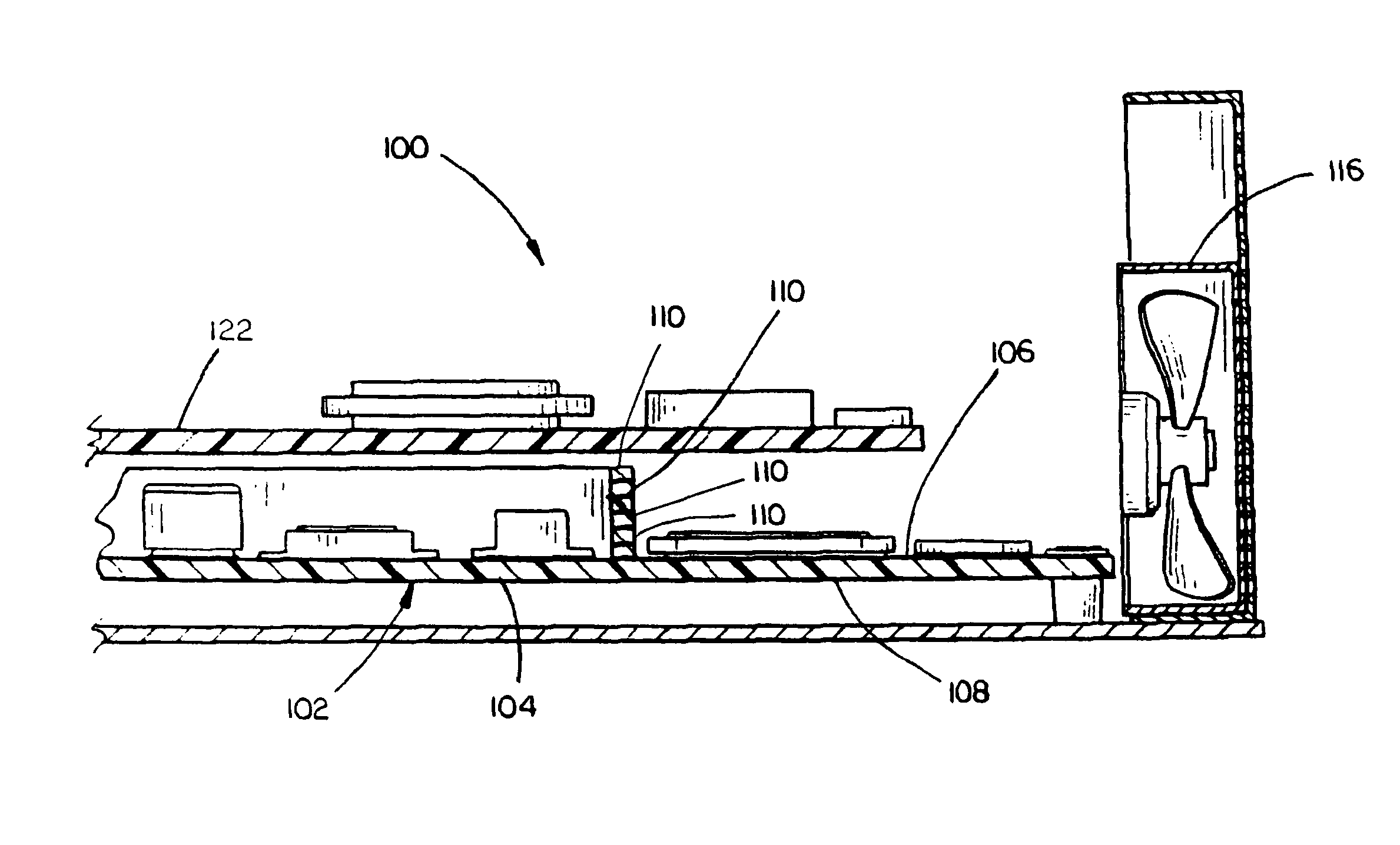
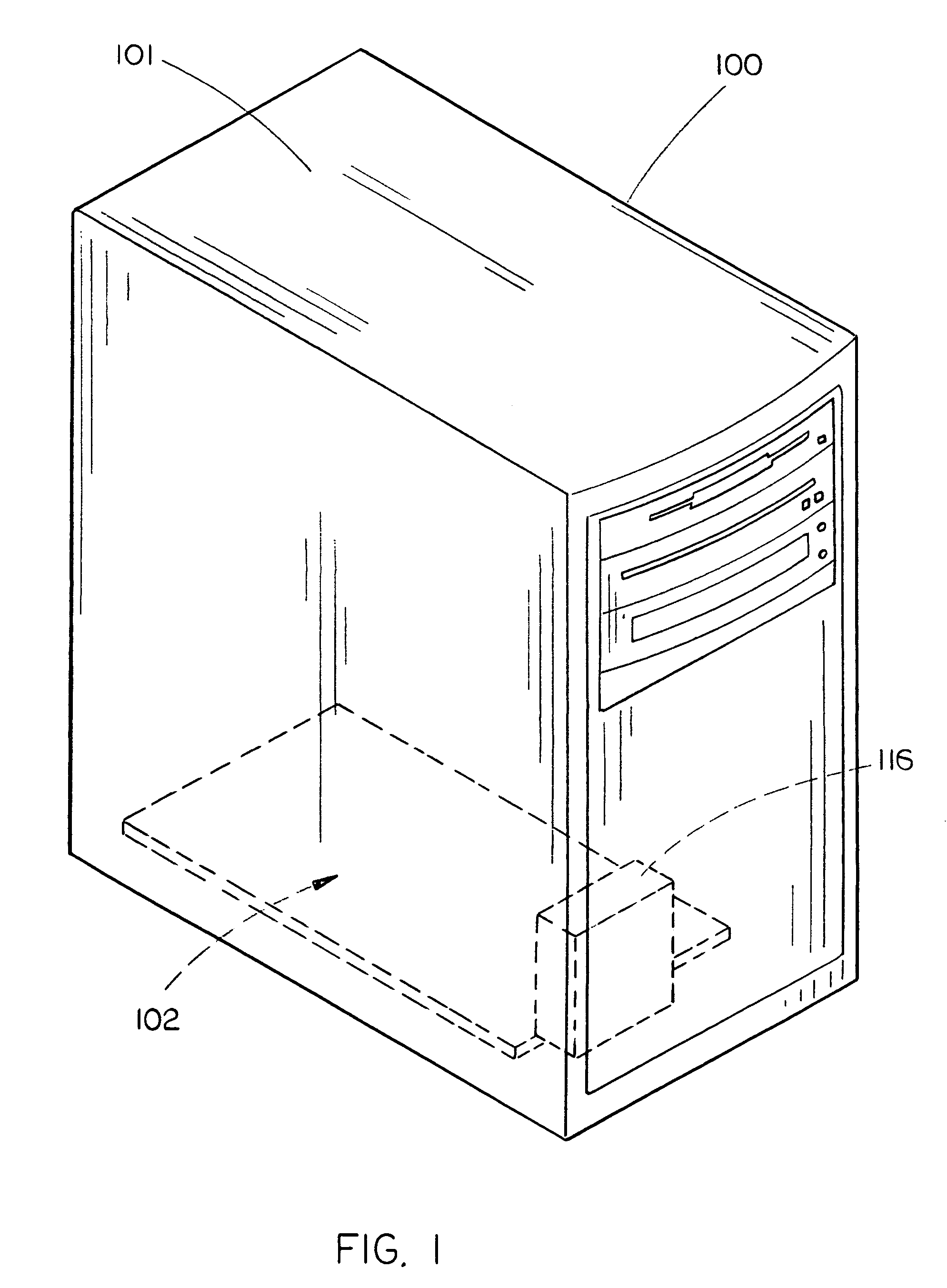
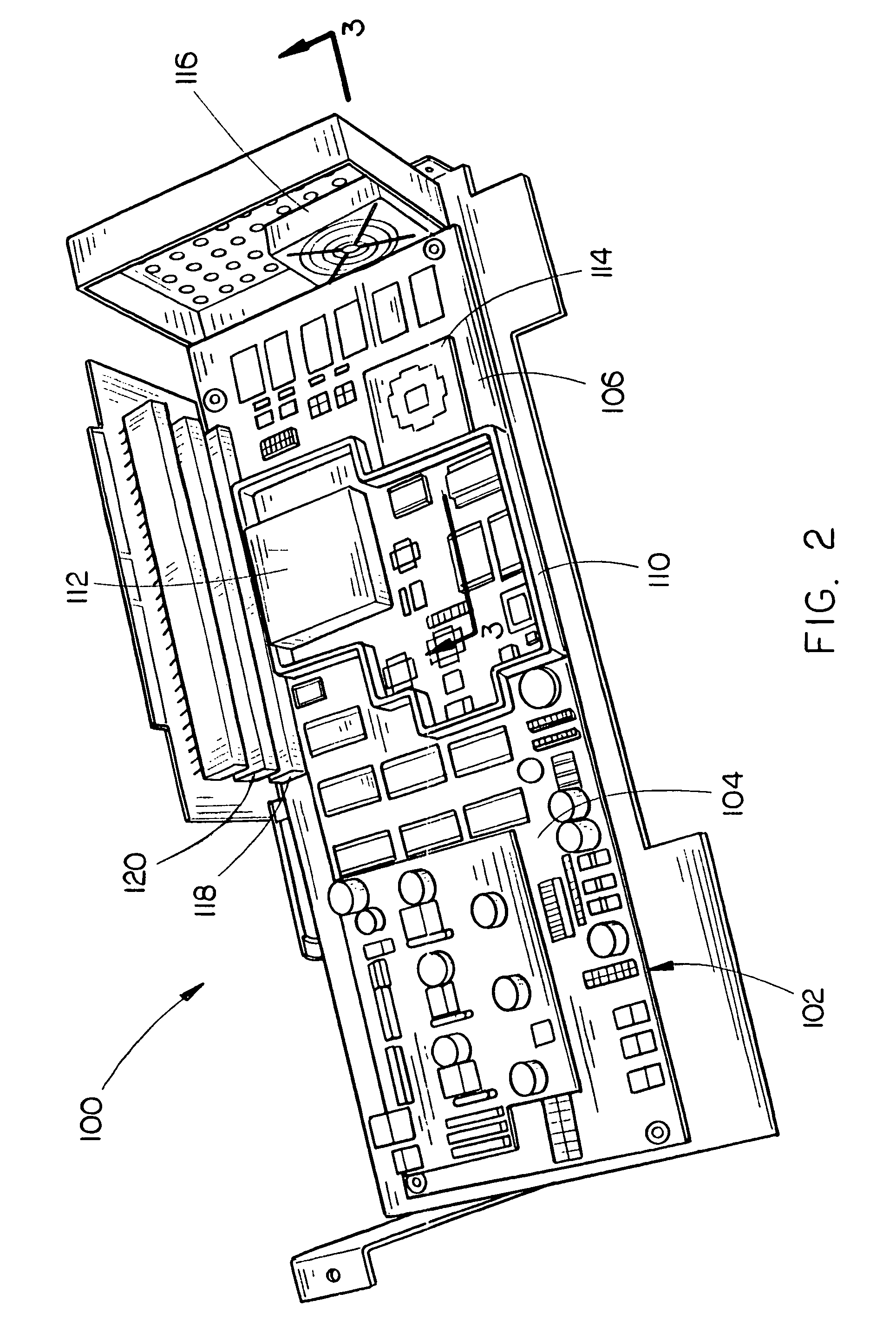
[0016]Referring generally to FIGS. 1 through 5, an electronic device 100 including a housing or chassis 101 enclosing or containing a printed circuit board 102 is described in accordance with exemplary embodiments of the present invention. The housing 101 further includes a cooling system for providing airflow for cooling components within the electronic device 100. For example, in the embodiments shown in FIGS. 1 through 5, the cooling system may comprise one or more system fans 116 for creating a flow of air through the housing 101 thereby causing airflow across the printed circuit board 102 for cooling the printed circuit board 102 and components mounted thereto. Alternatively, in other embodiments, the cooling system may employ convective cooling techniques which do not employ a system fan.

[0017]The printed circuit boa...


PUM


Abstract

An electronic device includes a printed circuit board having a wall deposited directly on a board serving as a base for a printed circuit. As the board is constructed, the wall is deposited on the board for controlling airflow. The wall controls airflow across the board and around components mounted to the board. The wall may be utilized for controlling airflow in combination with a second printed circuit board positioned adjacent to the first printed circuit board. The wall may be utilized for controlling various types of airflow, including airflow from sources including fans and convection, and from geometries including horizontal and vertical mounting geometries. The silicon wall may be utilized for preventing heat airflow generated by heat radiated from one component from impinging upon another component.

Description

FIELD OF THE INVENTION[0001]The present invention generally relates to the field of electronic devices employing printed circuit boards, and more particularly to a printed circuit board for an electronic device including a wall deposited directly on the board for controlling airflow across the board and its components.BACKGROUND OF THE INVENTION[0002]Printed circuit boards comprise thin boards of insulating material (e.g., fiberglass impregnated with epoxy resin, paper impregnated with phenolic resin, plastic, polyimide film, silicon, and materials including copper or aluminum cores) that serve as the base for a printed circuit, i.e., a pattern of connections, or traces, superimposed (printed) onto a non-conductive substrate. The connections are metal strips (e.g., copper), and the pattern is typically produced using silk screen printing, photoengraving, PCB Milling, and / or electroplating. Electronic components are fixed to the board and connected to the printed circuit with solder....

Claims


Application Information

Patent Timeline
Patent Type & Authority Patents(United States)
IPC IPC(8): H05K7/20
CPCG06F1/20H05K1/0272H05K1/0203H05K2201/09045H05K2201/09909
Inventor SLAGLE, RICHARD A.
Owner NETWORK APPLIANCE INC
Why Eureka
Try Eureka