Distributed scheduling method for multi-antenna wireless system

a wireless system and distributed scheduling technology, applied in the field of wireless communication systems, can solve the problems of reducing the scalability of the optimization process, and overwhelming the benefits so as to improve the scalability of the optimization process, and reduce the data overhead of the optimization process.

Active Publication Date: 2012-05-15
WISCONSIN ALUMNI RES FOUND
View PDF8 Cites 3 Cited by
  • Summary
  • Abstract
  • Description
  • Claims
  • Application Information

AI Technical Summary

Benefits of technology

[0014]The present invention provides a method of scheduling users in an MIMO system that addresses these two problems of mathematical intractability and communication overhead by offloading the optimization process to the individual receivers. This provides two benefits. First, as the number of users increases, the potential computational power also increases, improving the scalability of the optimization process. Second, by distributing the optimization process, the amount of data that must be communicated to a centralized source, the data overhead for optimization processes, is significantly reduced.
[0015]In a preferred embodiment, zero-forcing beam-forming is employed to simplify the channel vector calculations so that they can be easily handled by the computational power of current mobile receivers.
[0016]The invention also addresses the scheduling problem incrementally by only scheduling open channels and assuming a starting condition of the channels of currently enrolled mobile receivers. This comports with a general desire not to interrupt ongoing communications and greatly simplifies the search space for the optimization.

Problems solved by technology

Optimizations requiring an exhaustive search with a pool size as small as twelve in the time frames required by modern communication systems are currently impossible.
In addition to the mathematical complexity of the optimization process, the optimization requires a communication overhead, that is, additional data that must be communicated between the base station and mobile stations outside the data communicated by the users of the two nodes, for example, voice data in a phone system.
As the pool of users grows, this transmission overhead, to the extent that it subtracts from the aggregate data rate or other metric, can overwhelm the benefits obtainable from the optimization process.
Such mathematical approximations do not solve the problems of data overhead for large pool sizes M.

Method used


Image

  • Distributed scheduling method for multi-antenna wireless system
  • Distributed scheduling method for multi-antenna wireless system
  • Distributed scheduling method for multi-antenna wireless system

Examples


Embodiment Construction

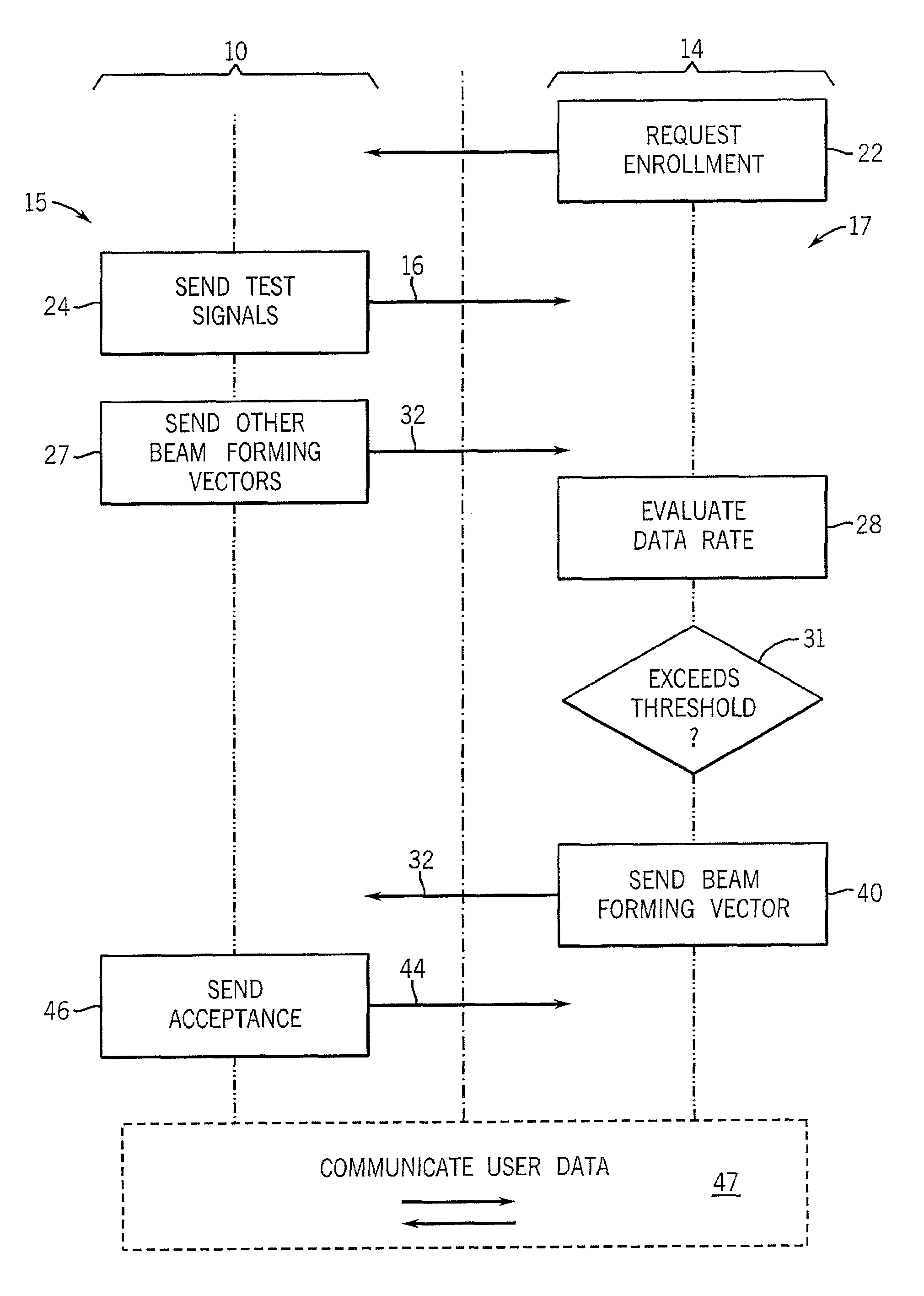
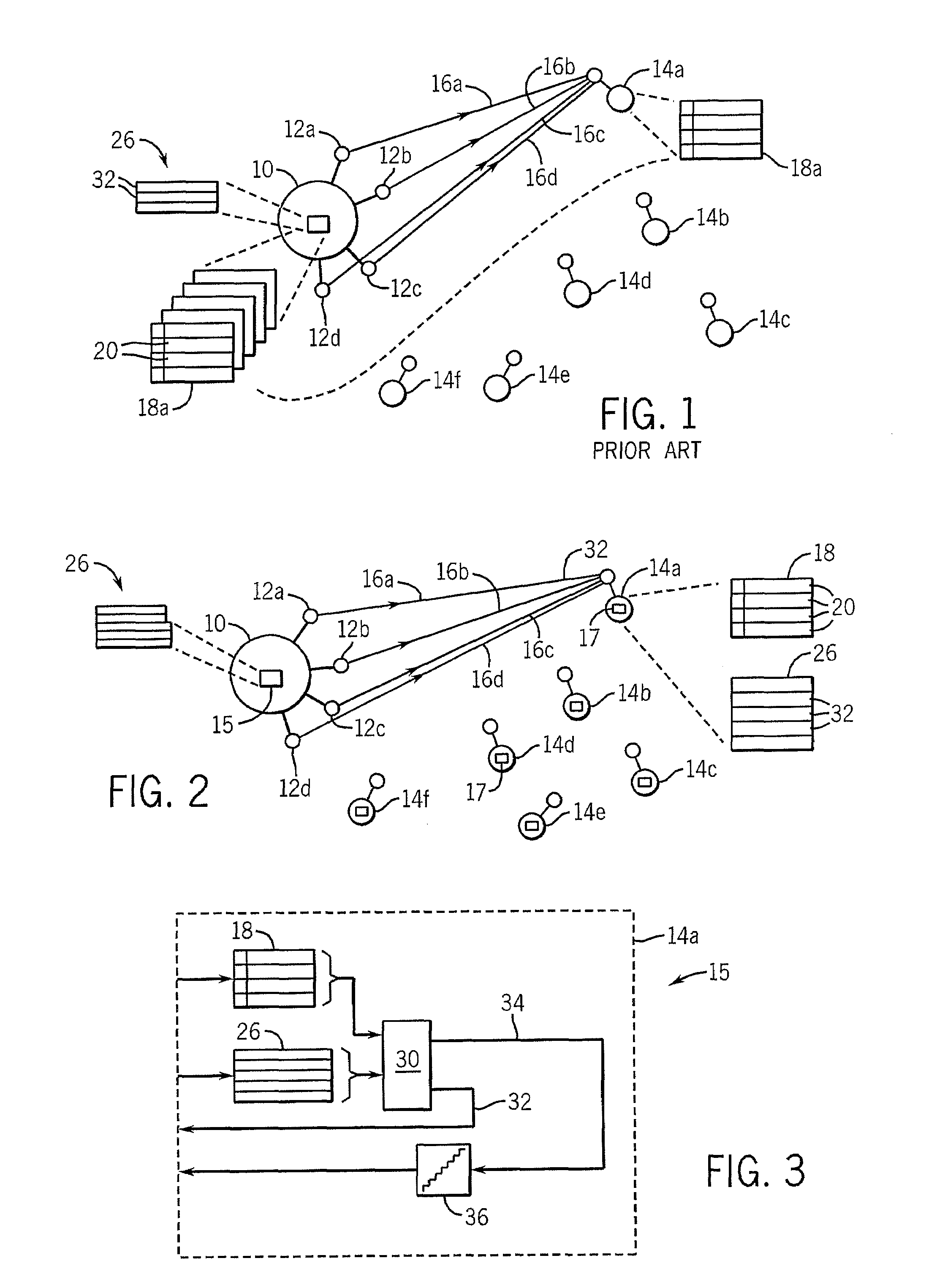
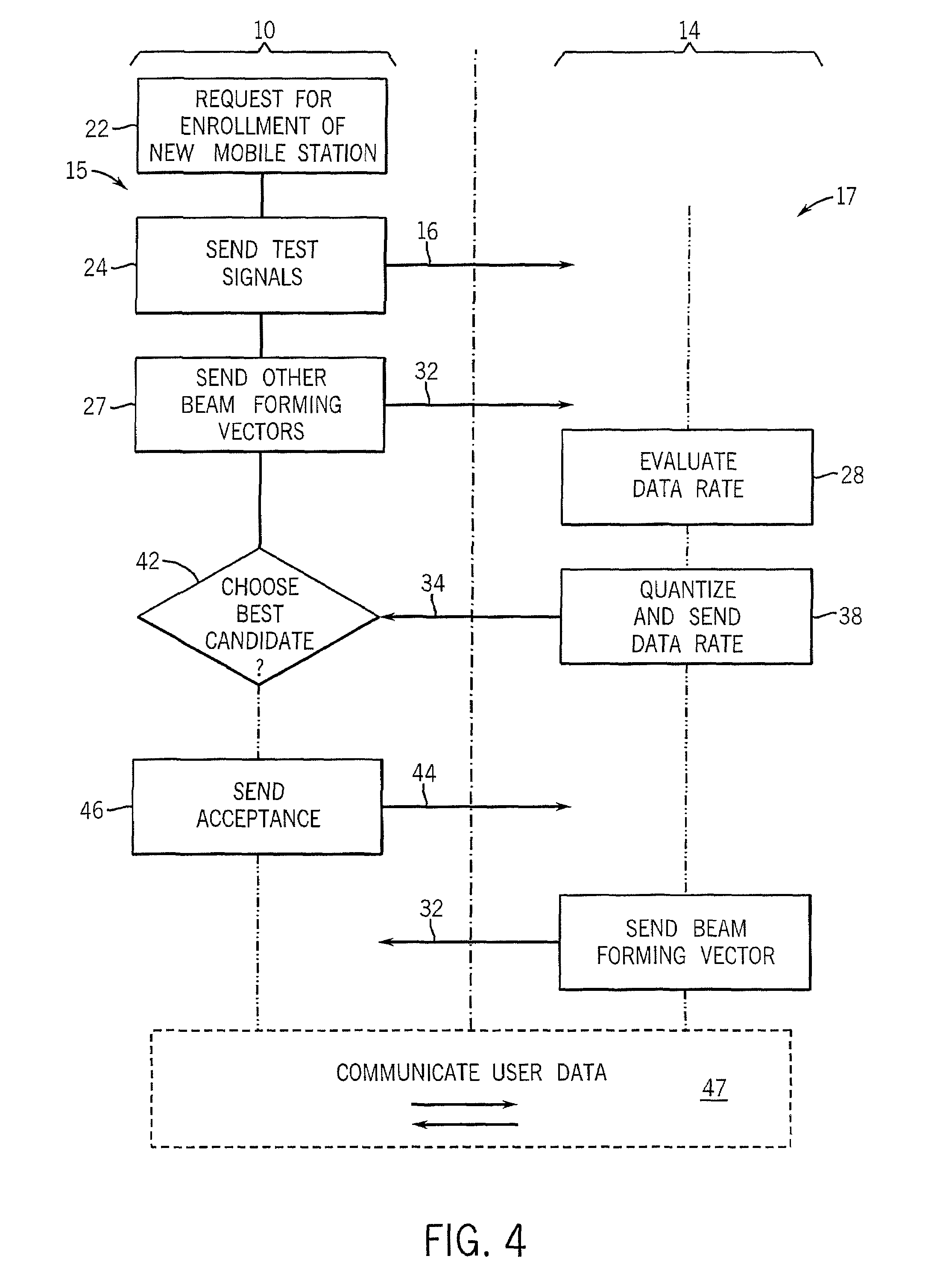
[0041]Referring now to FIG. 2, the present invention may employ a base station 10, for example, being a radio transceiver being part of a cellular telephone system or wireless local area system. The base station 10 may have multiple antennas 12a-12c that may communicate with a pool of mobile stations 14a-14f, being radio transceivers compatible with the base station 10.

[0042]Each of the base station 10 and mobile stations 14 may employ radio-frequency communication hardware, for example, suitable for time division multiplexing, frequency division multiplexing, and frequency hopping according to techniques well known in the art. The base station 10 incorporates a program 15 and the mobile stations 14a-14f incorporate programs 17 controlling their operation per the present invention as will now be described.

[0043]Referring now to FIGS. 2 and 4, at any given time, the base station 10 may receive data from a network intended for a new mobile station 14a, per process block 22, and effect...


PUM


Abstract

A channel allocation system for a beam-forming wireless network selects receivers to enroll in communication from a pool of candidate receivers, by off-loading a determination of the effects of adding each candidate receiver to the candidate receiver itself. In one embodiment, the candidate receivers nominate themselves for enrollment based on their determination of aggregate data rate changes resulting from their enrollment and the comparison of this aggregate data rate change against an estimate of the aggregate data rate changes of other candidate receivers.

Description

STATEMENT REGARDING FEDERALLY SPONSORED RESEARCH OR DEVELOPMENT[0001]This invention was made with United States government support awarded by the following agency: NSF 0519824. The United States has certain rights in this invention.CROSS-REFERENCE TO RELATED APPLICATIONS--BACKGROUND OF THE INVENTION[0002]The present invention relates to wireless communication systems having multi-antenna base stations, and, in particular, to a scheduling method for such wireless communication systems allowing improved multiple input multiple output (MIMO) operation.[0003]Multiple antenna wireless systems can increase the number of separate communication channels that can be provided between a given transmitter and receiver. Multiple antennas on either of a transmitter or receiver allow creation of channels that are spatially selective using a process termed “beam forming.” In multi-user beam forming, a beam-forming vector wi is created for each user i up to a maximum number of users or channels equa...

Claims


Application Information

Patent Timeline
Patent Type & Authority Patents(United States)
IPC IPC(8): H04W4/00H04L12/28H04J4/00
CPCH04W72/085H04B7/0617H04W72/0406H04W72/20H04W72/542
Inventor RAMANATHAN, PARMESWARANMUNDARATH, JAYAKRISHNAN C.VAN VEEN, BARRY
Owner WISCONSIN ALUMNI RES FOUND
Why Eureka
Try Eureka