Energy management apparatus and method

a technology of energy management and equipment, applied in the field of energy management techniques, can solve the problems of difficult to achieve both the target operating condition and the saving of energy consumption, and cannot be said that the above-mentioned means is a realistic solution

Inactive Publication Date: 2012-05-22
TOYOTA JIDOSHA KK
View PDF9 Cites 3 Cited by
  • Summary
  • Abstract
  • Description
  • Claims
  • Application Information

AI Technical Summary

Benefits of technology

[0008]It is a general object of the present invention to provide an improved and useful energy management apparatus in which the above-mentioned problems are eliminated.
[0009]A more specific object of the present invention is to provide an energy management apparatus which manages energy consumption of a machine, which has a supply part for supplying energy and a consume part for consuming the energy supplied by the supply part, so that the energy consumed by the consume part is positively saved.
[0011]1) An energy management apparatus that manages energy consumed in a machine having a supply part that supplies an energy and a consume part that consumes the energy supplied by the supply part, the energy management apparatus comprising: an operating part that operates the consume part by using the energy supplied by the supply part; an acquisition part that acquires an energy conversion characteristic, as an energy efficiency, from an input energy supplied to the consume part into an output energy output from the consume part; and a change part that changes an operating condition of the consume part based on the acquired energy efficiency so as to improve an actual value of the energy efficiency.
[0012]According to the present invention, the operating condition of the consume parts are changed in accordance with the energy efficiency of the consume part so that the actual value of the energy efficiency is improved. Therefore, according to the present invention, it becomes possible to optimize the operating condition of consume part so as to save energy consumed by the consume part.
[0017]According to the above-mentioned invention, the operating condition of the consume part is changed when at least the condition that the difference between the operation request to the consume part and the actual output of the consume part is equal to or smaller than a specified value is established, that is, when the condition that the operation request to the consume part is substantially achieved is established. Therefore, according to the above-mentioned invention, both the operation request and the energy consumption saving can be achieved easily for the same consume part.
[0037]13) An energy management method of managing energy consumed in a machine having a supply part that supplies an energy and a consume part that consumes the energy supplied by the supply part, the energy management method comprising: an operating step of operating the consume part by using the energy supplied by the supply part; an acquiring step of acquiring an energy conversion characteristic, as an energy efficiency, from an input energy supplied to the consume part into an output energy output from the consume part; and a changing step of changing an operating condition of the consume part based on the acquired energy efficiency so as to improve an actual value of the energy efficiency.

Problems solved by technology

In any case, energy consumed by a machine is limited, and, thus, there is a great demand for saving energy while achieving a target operating condition.
In such as case, it is not easy to achieve both the target operating condition and the saving of energy consumption.
However, judging from economical viewpoints or physical viewpoints such as weight, size, etc., it cannot be said that the above-mentioned means is a realistic solution.

Method used


Image

  • Energy management apparatus and method
  • Energy management apparatus and method
  • Energy management apparatus and method

Examples


Embodiment Construction

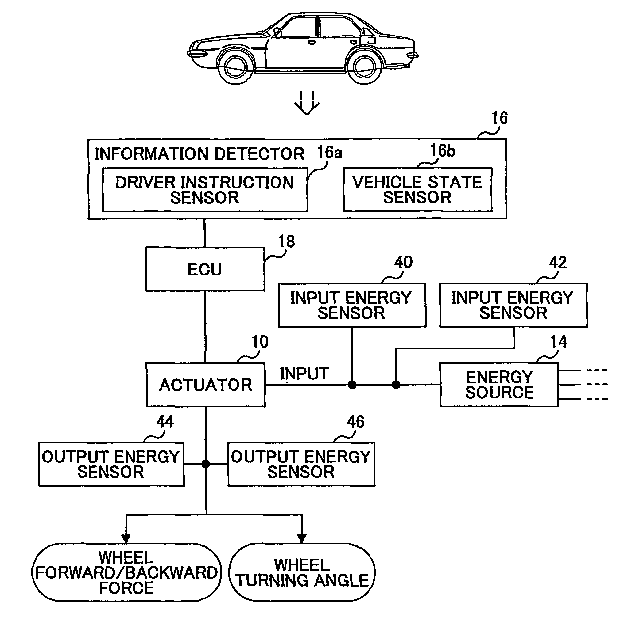
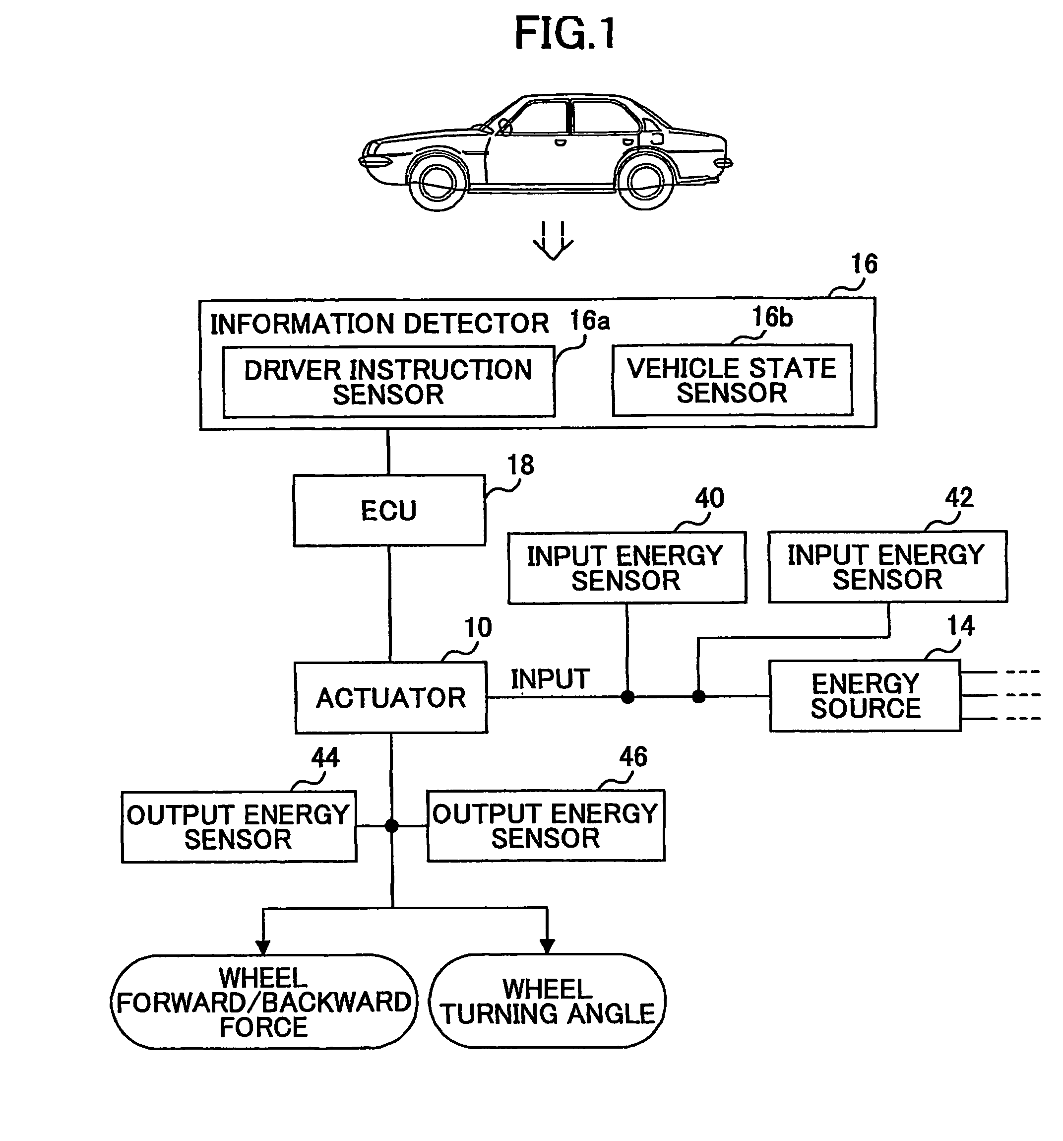
[0046]A description will now be given, with reference to the drawings, of an energy management apparatus according to an embodiment of the present invention.

[0047]FIG. 1 is a block diagram of a drive control system serving as an energy management apparatus according to the present invention. The drive control system shown in FIG. 1 is mounted in an automobile (hereinafter may be referred as “vehicle”) as a movable body, which is an example of machines. The automobile is equipped with a plurality of actuators 10 (only one actuator 10 is shown in FIG. 1 for the sake of simplification). The automobile is further equipped with an energy source 14 that supplies energy to each of the actuators 10. As the energy source 14, a fuel, a battery cell, a fuel cell, or an engine (internal combustion engine) may be used. The plurality of actuators 10 provided in the automobile may include the following actuators.

[0048](1) An engine which generates a mechanical energy by combusting a fuel.

[0049](2)...


PUM


Abstract

An energy management apparatus manages energy consumption of a machine, which has a supply part (14) for supplying energy and a consume part (10) for consuming the energy supplied by the supply part, so that the energy consumed by the consume part is positively saved. An operating part operates the consume part by using the energy supplied by the supply part. An acquisition part acquires an energy conversion characteristic, as an energy efficiency, from an input energy (40), (42) supplied to the consume part into an output energy output (44), (46) from the consume part. A change part changes an operating condition of the consume part based on the acquired energy efficiency so as to improve an actual value of the energy efficiency.

Description

TECHNICAL FIELD[0001]The present invention relates to energy management techniques and, more particularly, to an energy management technique to manage energy consumption of a machine having an energy supply part and an energy consuming part that consumes energy supplied by the energy supplying part.BACKGROUND ART[0002]There is known a technique of managing energy in a machine, which has a supply part for supplying energy and a consume part for consuming the energy supplied by the supply part. Such a technique is disclosed in, for example, Japanese Laid-Open Patent Application No. 8-507671. One example of the supply part is a battery cell as an electric-energy accumulating part, and another example is a generator as an electric-energy generating part. On the other hand, one example of the consume part is an electric motor that is driven to provide a drive force to a machine.[0003]In a machine that performs a work, energy is consumed to as to perform the work. The energy to perform a ...

Claims


Application Information

Patent Timeline
Patent Type & Authority Patents(United States)
IPC IPC(8): F26B3/00B60W10/06B60R16/02B60W10/08B60W10/26B60W20/00F02D29/02
CPCB60W10/26B60W50/0205B60W10/30B60W2540/10Y02T10/56Y02T10/84Y02T10/40B60R16/02B60W10/24
Inventor ISONO, HIROSHI
Owner TOYOTA JIDOSHA KK
Why Eureka
Try Eureka