Refrigeration system

a refrigeration system and refrigeration technology, applied in the direction of refrigerating machines, fluid circulation arrangements, lighting and heating apparatus, etc., can solve the problem of excessive temperature of discharged refrigerant, achieve the effect of reducing compression heat, increasing compressor efficiency, and increasing cooling capacity of refrigeration systems

Active Publication Date: 2012-05-22
COPELAND LP
View PDF61 Cites 20 Cited by
  • Summary
  • Abstract
  • Description
  • Claims
  • Application Information

AI Technical Summary

Benefits of technology

[0003]Compressors are utilized to compress refrigerant for refrigeration systems, such as air conditioning, refrigeration, etc. During the compression of the refrigerant within the compressor, a significant quantity of heat can be generated. This heat can result in the temperature of the discharged refrigerant being excessively high. A reduction in the discharge temperature of the refrigerant can increase the cooling capacity of the refrigeration system. Additionally, a reduction of the compression heat can increase the efficiency of the compressor. Thus, it would be advantageous to reduce the temperature during the compression process. Furthermore, it would be advantageous to reduce the temperature of the discharged refrigerant exiting the compressor. It would be even more advantageous if the refrigerant compression approached quasi-isothermal compression.
[0004]A refrigeration system according to the present teachings can incorporate a liquid-injection system that provides a cooling liquid to an intermediate-pressure location of the compressor. The cooling liquid can absorb the heat of compression during the compression of the refrigerant flowing therethrough. The cooling liquid can be externally separated from the refrigerant flow and injected back into the intermediate-pressure location. The cooling liquid can thereby advantageously decrease the temperature of the compression process and the temperature of the refrigerant being discharged by the compressor. The liquid-injection system can result in an increased cooling capacity and / or an increased efficiency for the refrigeration system.
[0005]A refrigeration system according to the present teachings can also include vapor injection of a refrigerant flow into an intermediate-pressure location of the compressor through an economizer circuit. The incorporation of the vapor injection in conjunction with the cooling-liquid injection can advantageously increase the cooling capacity and / or efficiency of the refrigeration system and the performance of the compressor.

Problems solved by technology

This heat can result in the temperature of the discharged refrigerant being excessively high.

Method used


Image

  • Refrigeration system
  • Refrigeration system
  • Refrigeration system

Examples


Embodiment Construction

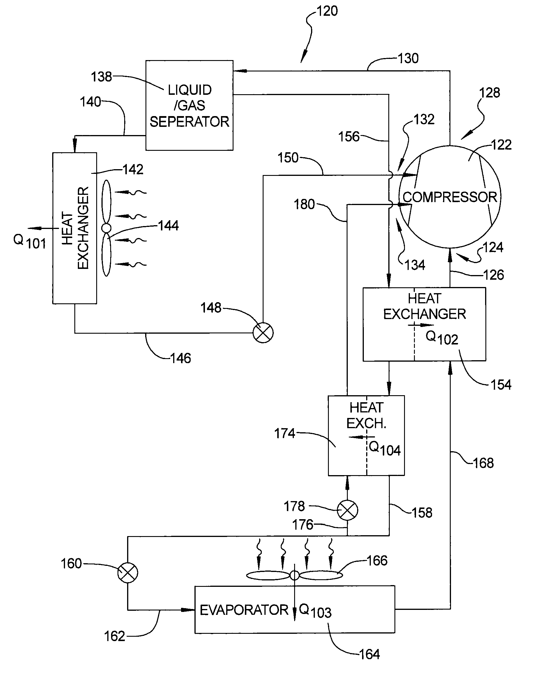
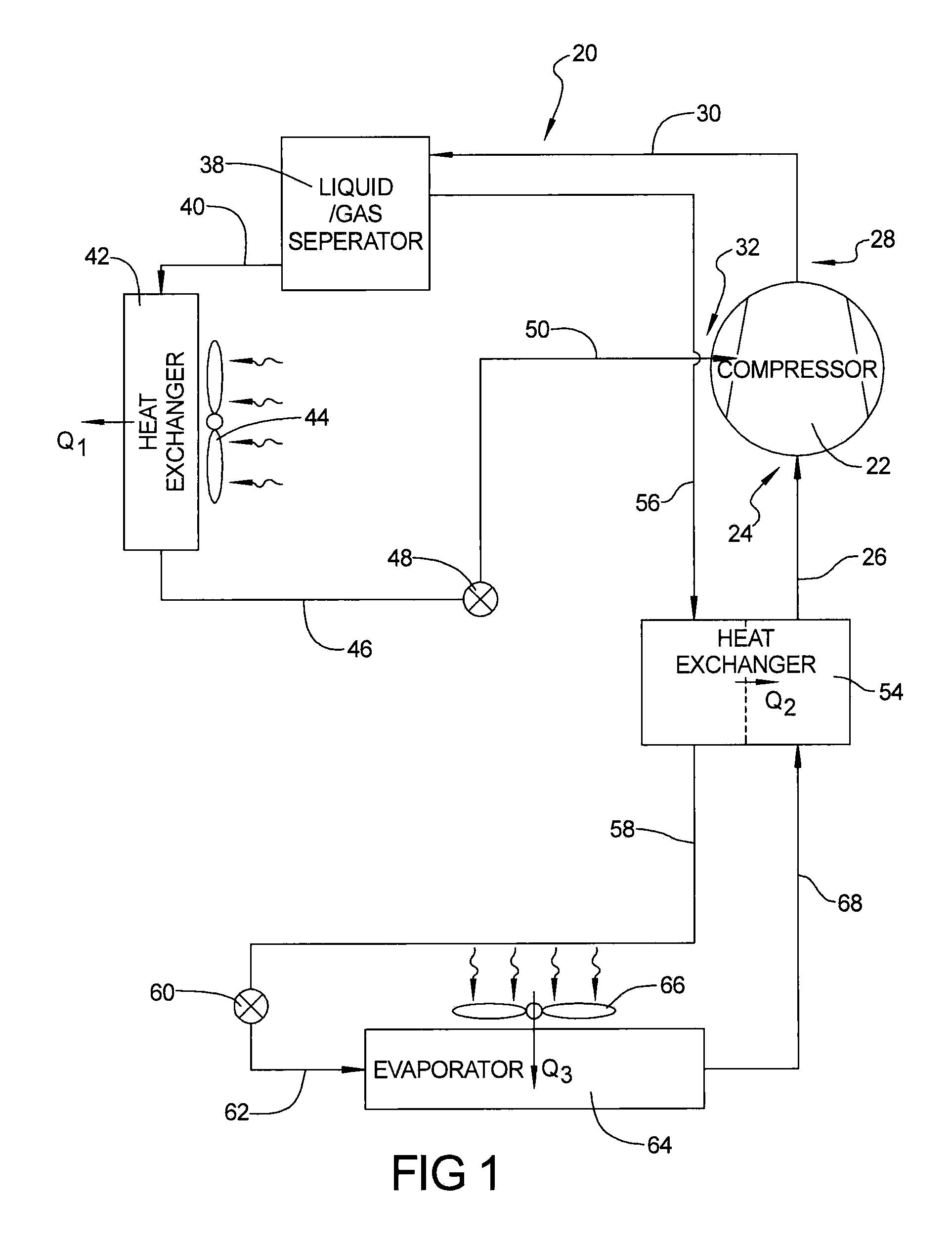
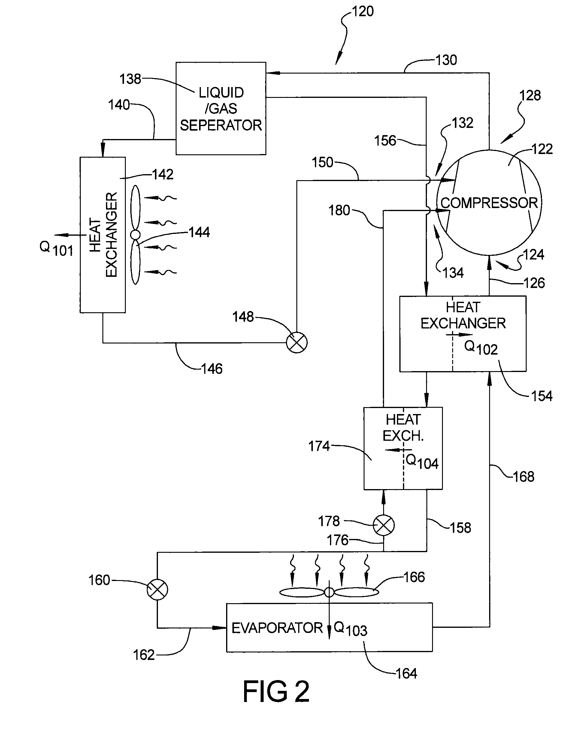
[0012]The following description is merely exemplary in nature and is not intended to limit the present disclosure, application, or uses. It should be understood that throughout the drawings, corresponding reference numerals (e.g., 20, 120, 220 and 30, 130, 230, etc.) indicate like or corresponding parts and features.

[0013]Referring to FIG. 1, a refrigeration system 20 according to the present teachings is shown. Refrigeration system 20 is a vapor-compression refrigeration system that is sealed and filled with a refrigerant. Refrigeration system 20 can be configured for a trans-critical refrigeration cycle wherein the refrigerant is at a temperature above its critical temperature during a part of the cycle, thus being in the vapor form regardless of the pressure, and is below its critical temperature in the other parts of the cycle, thereby enabling the refrigerant to be in liquid form. The trans-critical refrigerant can be CO2 and other trans-critical refrigerants. It should be appr...


PUM


Abstract

A refrigeration system can incorporate a liquid-injection system that can provide a cooling liquid to an intermediate-pressure location of the compressor. The cooling liquid can absorb the heat of compression during the compression of the refrigerant flowing therethrough. The refrigeration system can include an economizer circuit that injects a refrigerant vapor into an intermediate-pressure location of the compressor in conjunction with the injection of the cooling liquid. The incorporation of the vapor injection in conjunction with the cooling-liquid injection can advantageously increase the cooling capacity and / or efficiency of the refrigeration system and the performance of the compressor.

Description

FIELD[0001]The present teachings relate generally to refrigeration systems and, more particularly, to refrigeration systems with liquid injection.BACKGROUND AND SUMMARY[0002]The statements in this section merely provide background information related to the present teachings and may not constitute prior art.[0003]Compressors are utilized to compress refrigerant for refrigeration systems, such as air conditioning, refrigeration, etc. During the compression of the refrigerant within the compressor, a significant quantity of heat can be generated. This heat can result in the temperature of the discharged refrigerant being excessively high. A reduction in the discharge temperature of the refrigerant can increase the cooling capacity of the refrigeration system. Additionally, a reduction of the compression heat can increase the efficiency of the compressor. Thus, it would be advantageous to reduce the temperature during the compression process. Furthermore, it would be advantageous to re...

Claims


Application Information

Patent Timeline
Patent Type & Authority Patents(United States)
IPC IPC(8): F25B43/02F25B41/00F25B43/00F25B31/00
CPCF25B31/002F25B43/02F25B1/10F25B40/00F25B2400/13F25B2400/23
Inventor IGNATIEV, KIRILL
Owner COPELAND LP
Why Eureka
Try Eureka