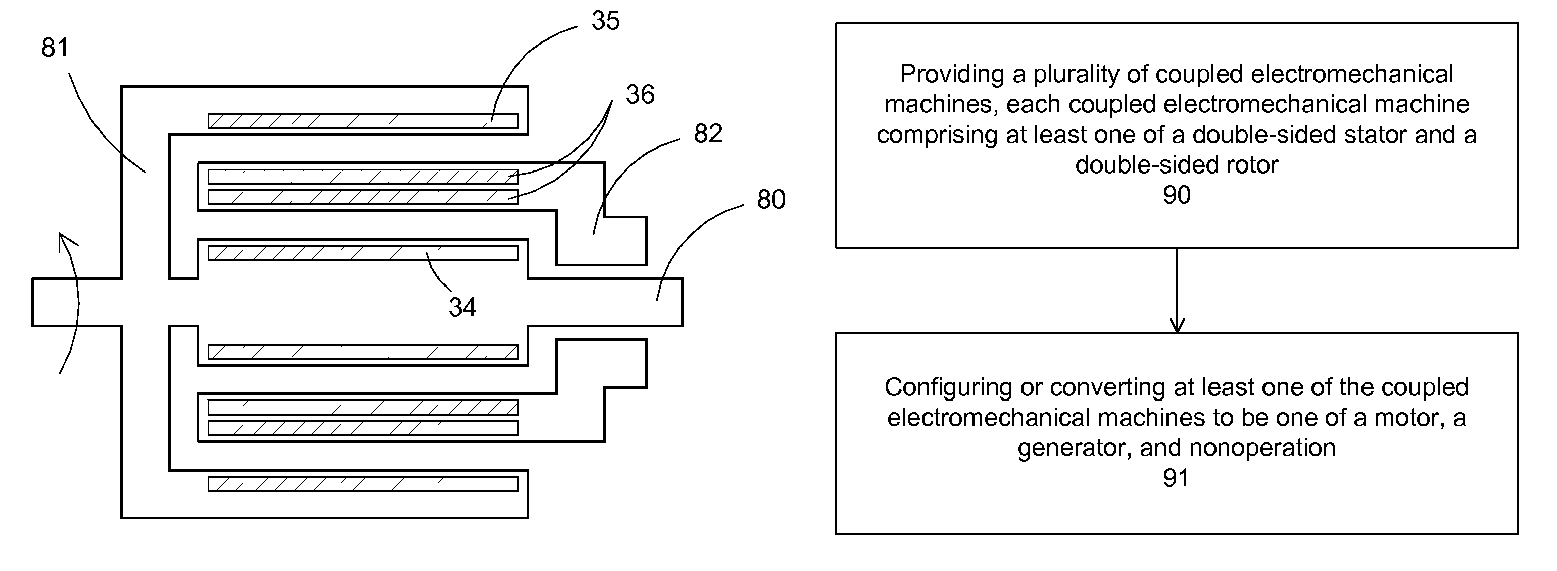
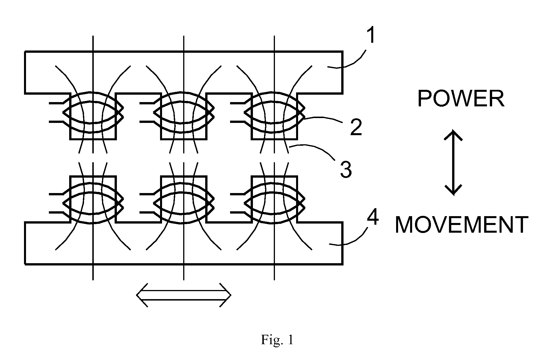
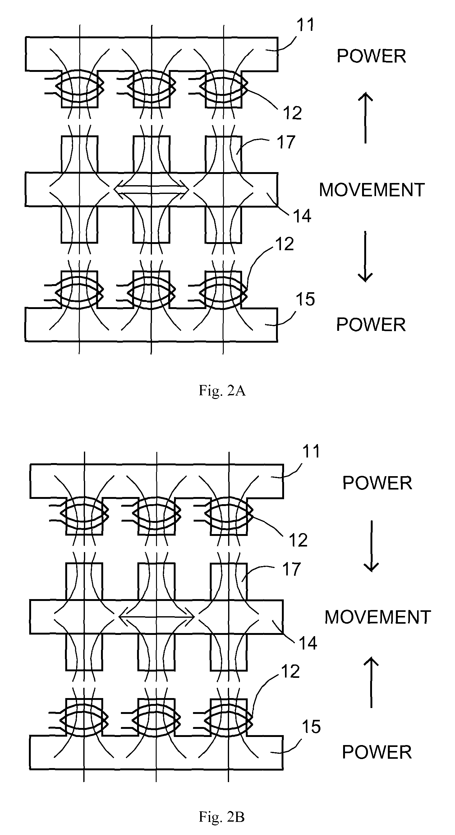
[0009]In an aspect, the present composite electromechanical machine comprises at least two rotor / stator pairs integrated together. In an aspect, the two stators from the two rotor / stator pairs form a double-sided stator having an inner stator side and an outer stator side. The composite double-sided stator can replace two separate inner stator and outer stator in coupling with an inner rotor and an outer rotor, respectively. In an aspect, the two rotors from the two rotor / stator pairs form a double-sided rotor having an inner rotor side and an outer rotor side. The composite double-sided rotor can replace two separate inner rotor and outer rotor in coupling with an inner stator and an outer stator, respectively. The stator and the rotors can comprise either a permanent magnet or a winding to generate a magnetic field. If the rotors comprise winding, a brush mechanism can be included to accommodate the winding. The composite electromechanical machine can be a brushless machine with the rotor comprising of at least one permanent magnet, and the double-sided stator comprising stator winding(s). The composite electromechanical machine can be a brush machine with the rotor (inner rotor, outer rotor or both rotors) comprising a winding, and the double-sided stator comprising of at least one permanent magnet. The composite electromechanical machine further comprises a controller coupled to the rotor / stator pairs to configure at least a winding of the rotor / stator pairs. Configuring a winding can configure or change the functionality or the characteristics of the rotor / stator pairs.
[0010]In an embodiment, configuring or changing the functionality of a rotor / stator pair includes making the rotor / stator pair become either a nonoperation part, a motor or a generator. For example, changing the functionality of a rotor / stator pair can include changing a motor configuration to a generator configuration, and vice versa. The controller can change the function of the composite electromechanical machine to accommodate different situations. For example, a composite electromechanical machine can comprise two rotor / stator pairs. For high motor power, the controller can configure the two rotor / stator pairs to be motor, combining their power. For reducing power, the controller can configure one rotor / stator pair to be nonoperation, such as no power or a small power to offset the magnetic braking is supplied to the rotor, the stator, or rotor / stator pair, leaving one rotor / stator pair to carry the load. If the two motor / stator pairs have different power levels, there can be two levels of power outputs, a low power with the stronger rotor / stator pair becoming nonoperation, and a high power with the weaker rotor / stator pair nonoperation. For a faster reduction of power or speed, the controller can configure one rotor / stator pair to be a generator, essentially providing a braking force on the remaining motor. This configuration can conserve energy, storing the braking power of the motor into electrical power of the generator. Similarly, if the two motor / stator pairs have different power levels, there can be two levels of braking power, a higher braking power with the high power rotor / stator pair nonoperation, and a lower braking power with the low power rotor / stator pair nonoperation. Additionally, anyone or a combination thereof can reverse the rotation of the motor for even stronger braking and coming to a complete stop.
[0013]In an embodiment, the present invention discloses a method for configuring a composite electromechanical machine, which preferably comprises at least a double-sided rotor or stator. The machine could be a motor or a generator. The methodology turns a rotor / stator pair to nonoperation configuration, to a motor configuration, or to a generator configuration. In an aspect, the method comprises a monitoring of a desired output. If a higher output is required, additional rotor / stator pairs can be configured to add power. If a lower output is required, one or more rotor / stator pairs can be configured to be nonoperation, reducing the power output. Alternatively, one or more rotor / stator pairs can be configured to be a brake for quickly reducing power. For example, for a motor operation, converting a rotor / stator pair from a motor configuration to a generator configuration provides a braking operation to the motor. For a generator operation, adding additional rotor / stator pairs to the generator can also provide a braking operation. The brake can conserve power through the use of power generated from the generator.