
Adjustable curved fence assembly

a conveyor and curved technology, applied in the field of conveyors, can solve the problems of difficult to present a smooth guide surface to bottles, complicated mechanical structure of fences, and limited use of curved fences, and achieve the effect of reducing the force acting

Active Publication Date: 2012-05-29
APX SEETECH SYST INC
View PDF18 Cites 27 Cited by
  • Summary
  • Abstract
  • Description
  • Claims
  • Application Information

AI Technical Summary

Benefits of technology

[0011]The actuators axes are preferably parallel with one another and parallel with an angular centerline of the curved conveyor section. This assists in displacing the ends of the curved guide fence with minimum application of force.
[0013]Actuation of the actuators to change the curvature of the curved guide fence and the displacement of the side fence can be under the automatic control of a control system. The control system can introduce a time delay between displacement of the side fence and actuation of the actuators to reduce the forces acting on the actuators when moving the curved guide fence.

Problems solved by technology

Such fences are mechanically complex, and it can be difficult to present a smooth guide surface to the bottles moving along the fence.
These curved fences are limited to use where only relatively small changes in radius (for example, one or two millimeters) are required.
Known adjustable curved fences do not offer the adjustment capabilities needed for relatively sharp conveyor turns.

Method used


Image

  • Adjustable curved fence assembly
  • Adjustable curved fence assembly
  • Adjustable curved fence assembly

Examples


Embodiment Construction

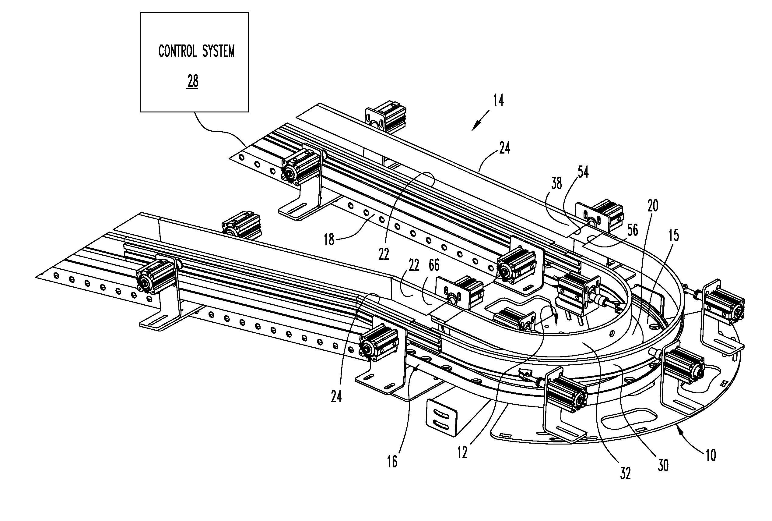
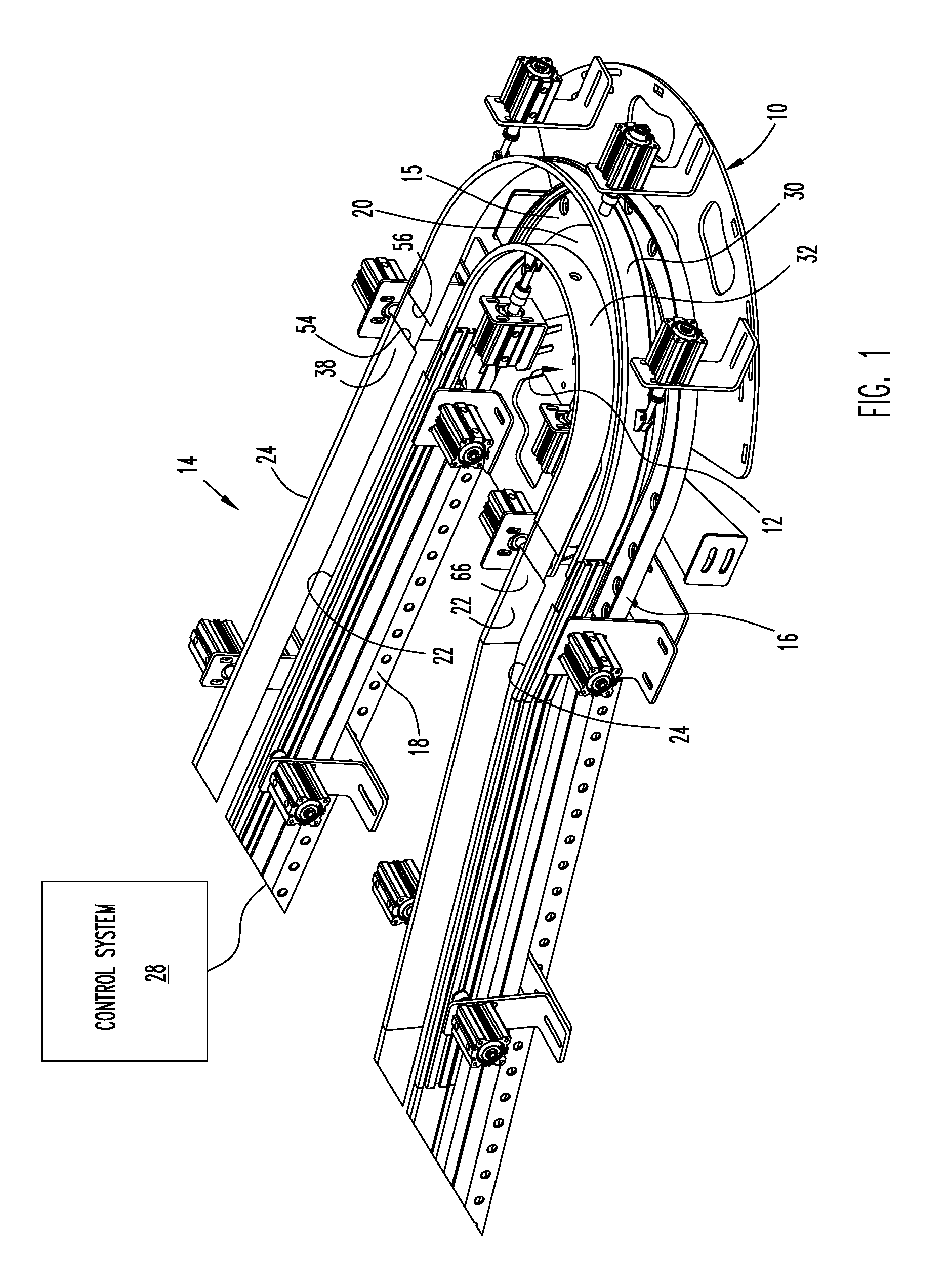
[0021]FIGS. 1-3 illustrate an adjustable curved fence apparatus 10 and an adjustable curved fence apparatus 12, each apparatus 10, 12 in accordance with the present invention, attached to an otherwise conventional flexible chain conveyor 14. The illustrated conveyor 14 conveys blow-molded plastic bottles received from a blow molding machine (not shown) and includes a flexible conveyor chain 15 that travels along a pair of parallel straight conveyor sections 16, 18 joined by a horizontal 180-degree wheel bend 20.

[0022]Bottles are guided along the straight conveyor sections 16, in a conventional manner by pairs of inner and outer side fences 22, 24 located on opposite sides of each conveyor straight section 16, 18. Each side fence 22, 24 is connected to a respective set of pneumatic cylinders 26 that translate the side fence 22 or 24 in a direction perpendicular to the side fence between extended and retracted positions of the fence. The pneumatic cylinders are connected to a control ...


PUM


Abstract

An adjustable curved fence assembly for a conveyor includes a curved guide fence and a number of pneumatic cylinders attached to the curved guide fence. The cylinder piston rods move between extended and retracted positions to change the radius of curvature of the curved guide fence.

Description

FIELD OF THE INVENTION[0001]The invention relates to conveyors for transporting articles along a conveyor path, and more specifically, to an adjustable curved fence assembly for a conveyor.BACKGROUND OF THE INVENTION[0002]Conveyors are used in the manufacture of plastic blow-molded bottles to transport the bottles ejected from a blow molding machine to cooling and processing stations. A bottle conveyor typically includes a conveyor belt or chain moving through straight conveyor sections joined by curved conveyor sections. Guide fences extend along both sides of the conveyor to stabilize the bottles and to ensure the proper orientation of the bottles during transportation and processing. The spacing between the fences is adjustable to enable the conveyor belt to convey different sized bottles of varying size and capacity.[0003]Adjusting the spacing of a curved fence may be accomplished by rotating the fence around an axis of rotation. This changes the vertical position of the fence w...

Claims


Application Information

Patent Timeline
Patent Type & Authority Patents(United States)
IPC IPC(8): B65G21/20
CPCB65G21/2072
Inventor BURCHELL, VICTOR HOWARDMOFFITT, JAMES HARPER
Owner APX SEETECH SYST INC
Features
  • Generate Ideas
  • Intellectual Property
  • Life Sciences
  • Materials
  • Tech Scout
  • Unparalleled Data Quality
  • Higher Quality Content
  • 60% Fewer Hallucinations
Learn More