Slab leveling system and method

a technology of leveling system and slab, applied in the direction of roads, roads, roads, etc., can solve the problems of uneven slab, cracks in the slab, and uneven concrete slab, and achieve the effects of convenient operation, high transportability, and economic and efficient operation

Inactive Publication Date: 2012-05-29
ASPLIN CHARLES LEE
View PDF30 Cites 23 Cited by
  • Summary
  • Abstract
  • Description
  • Claims
  • Application Information

AI Technical Summary

Benefits of technology

[0007]It is an additional objective of the present invention to provide such a method of repairing driveways or other similar slabs which is economical and efficient in operation.
[0008]It is a further objective of the present invention to provide such a method of repairing sidewalks that is highly transportable and that can be easily operated.
[0009]These objectives are accomplished by the use of a portable high volume air compressor that is connected to a sand storage tank by the use of a high pressure air line. The connection at the sand storage tank is accomplished through an air manifold which is primarily a splitter mechanism which allows the single line of air flow from the air compressor to be diverted to a number of possible different paths. One of these possible paths is through the manifold bleed line which extends up over the sand tank and serves the purpose of providing a mechanism by which any excess or unneeded air pressure existing at the manifold can be vented from the system. The manifold a

Problems solved by technology

Regardless of the care and skill used in the initial construction, concrete slabs tend to become misaligned over time due to different rates of settlement of the earth.
Uplift from freeze/thaw cycles or tree root lifting are also common causes of slab misalignment.
These problems cause cracks in the slab to develop and can also cause step-like structures to occur between sections of the slab.
The end result of this condition is the creation of hazards to users and liability for those who are responsible for their care.
Additionally, the uneven slabs

Method used


Image

  • Slab leveling system and method
  • Slab leveling system and method
  • Slab leveling system and method

Examples


Embodiment Construction

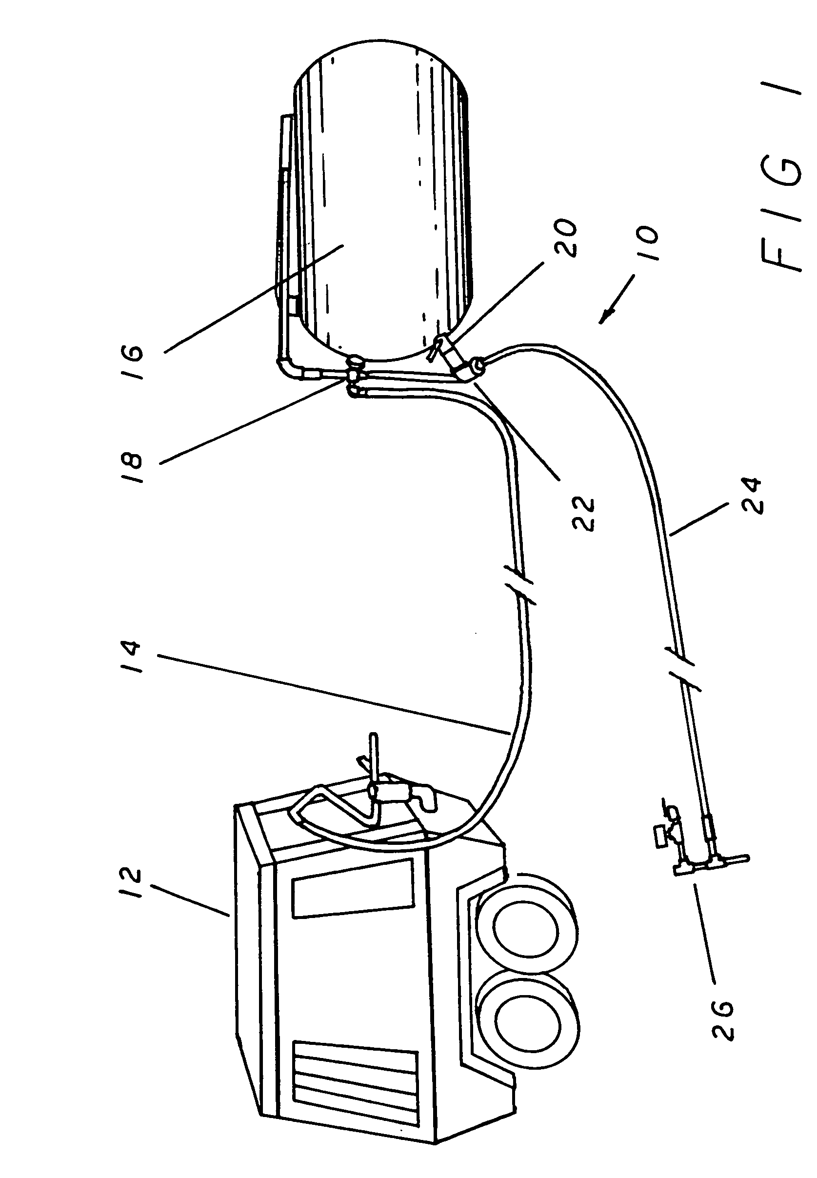
[0022]Referring now to the drawings, and more specifically to FIG. 1, slab leveling system 10 is made up of three primary components. The first of these is a high volume air compressor 12 which is typically a transportable device having independent wheels and a trailer tongue by which it is pulled to and from a work site. Additionally, the air compressor is most commonly powered by a small gasoline or diesel engine which allows it to be operated independently without the need for an outside power source.

[0023]The high volume air compressor 12 is connected to the second primary component of the invention, the sand storage tank 16, by the compressor to tank air line 14 which is simply a length of high pressure air hose that is of an inside diameter that is sufficient to handle the volume of air that is required for the efficient operation of the invention. The connection at the sand storage tank 16 is facilitated by the use of the tank manifold 18 which is a threaded cross apparatus w...


PUM


Abstract

A system for leveling a slab by raising and filling in voids under the slab. A mixture of compressed air and well dried sand is pumped through hose to a gun nozzle. The slab to be leveled is supplied with at least one hole for receiving the gun nozzle in a fluid tight connection. The compressed air is used to lift the slab while the sand is used to fill the void and keep the slab in a level position. The operator may supply successive burst of pressure to lift the slab as needed, while adjusting the air and sand flow. Finally, the gun nozzle is removed from the hole which is then patched thus, completing the repair of the damaged slab.

Description

BACKGROUND OF THE INVENTION[0001]The present invention relates to a method of leveling an existing concrete slab which has had portions settle into the ground so as to become uneven over time. More specifically, to a method of carefully raising a section of the sunken slab so as not to damage the section and allow for the injection of pressurized mason's sand into the cavity created between the bottom of the uneven slab and the settled ground.[0002]Regardless of the care and skill used in the initial construction, concrete slabs tend to become misaligned over time due to different rates of settlement of the earth. Uplift from freeze / thaw cycles or tree root lifting are also common causes of slab misalignment. These problems cause cracks in the slab to develop and can also cause step-like structures to occur between sections of the slab. The end result of this condition is the creation of hazards to users and liability for those who are responsible for their care. Additionally, the u...

Claims


Application Information

Patent Timeline
IPC IPC(8): E01C23/10
CPCE01C23/10
Inventor ASPLIN, CHARLES LEE
Owner ASPLIN CHARLES LEE
Why Eureka
Try Eureka