Scroll-type fluid machine that reduces centrifugal force of an orbiting scroll

a fluid machine and scroll-type technology, applied in machines/engines, couplings, liquid fuel engines, etc., can solve the problems of lowering the durability of the auxiliary crank device, and achieve the effect of reducing the centrifugal force of the orbiting scroll

Inactive Publication Date: 2012-05-29
HITACHI LTD
View PDF6 Cites 18 Cited by
  • Summary
  • Abstract
  • Description
  • Claims
  • Application Information

AI Technical Summary

Benefits of technology

[0008]The present invention has been made in light of the above problems, and it is an object of the present invention to provide a scroll-type fluid machine that can reduce centrifugal force of an orbiting scroll, which is applied to an auxiliary crank device.

Problems solved by technology

Accordingly, in case, for example, the orbiting scroll moves in an orbital manner at a high speed, excessive centrifugal force may apply to the auxiliary crank device, thereby possibly lowering durability of the auxiliary crank device.

Method used


Image

  • Scroll-type fluid machine that reduces centrifugal force of an orbiting scroll
  • Scroll-type fluid machine that reduces centrifugal force of an orbiting scroll
  • Scroll-type fluid machine that reduces centrifugal force of an orbiting scroll

Examples


first embodiment

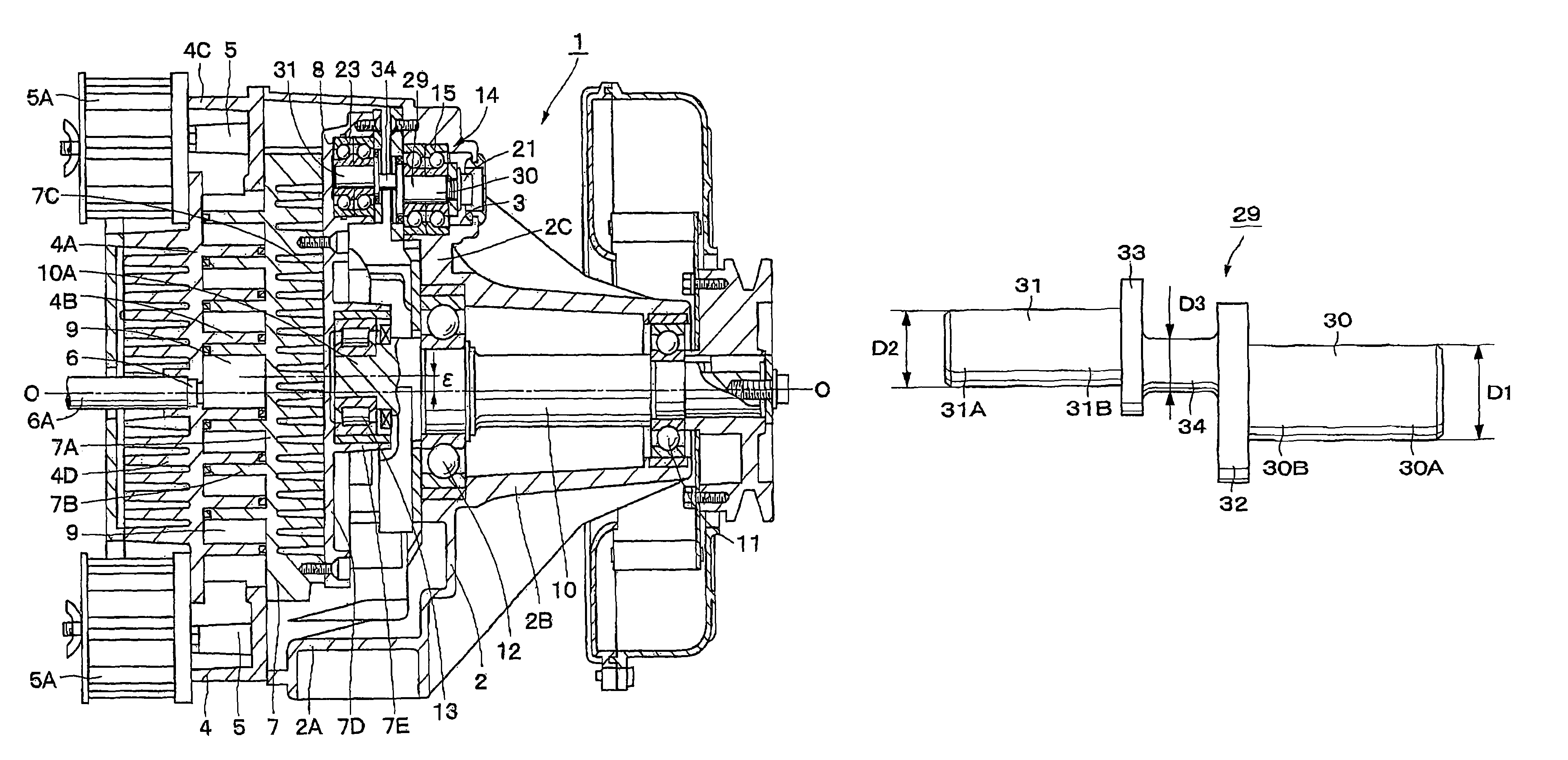
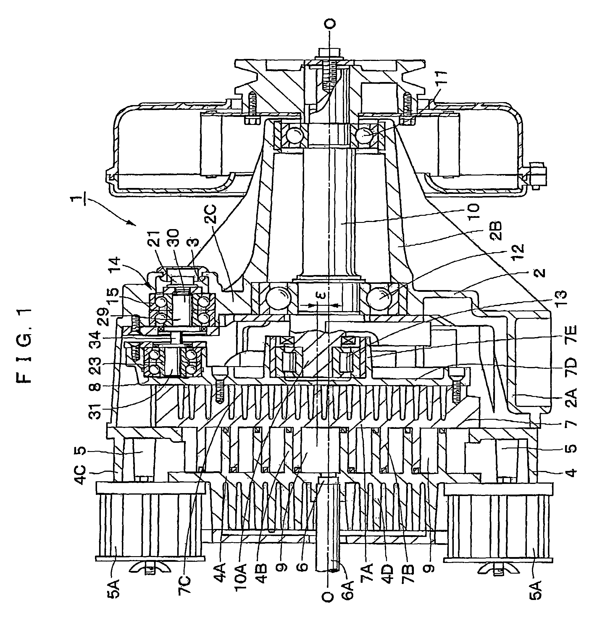
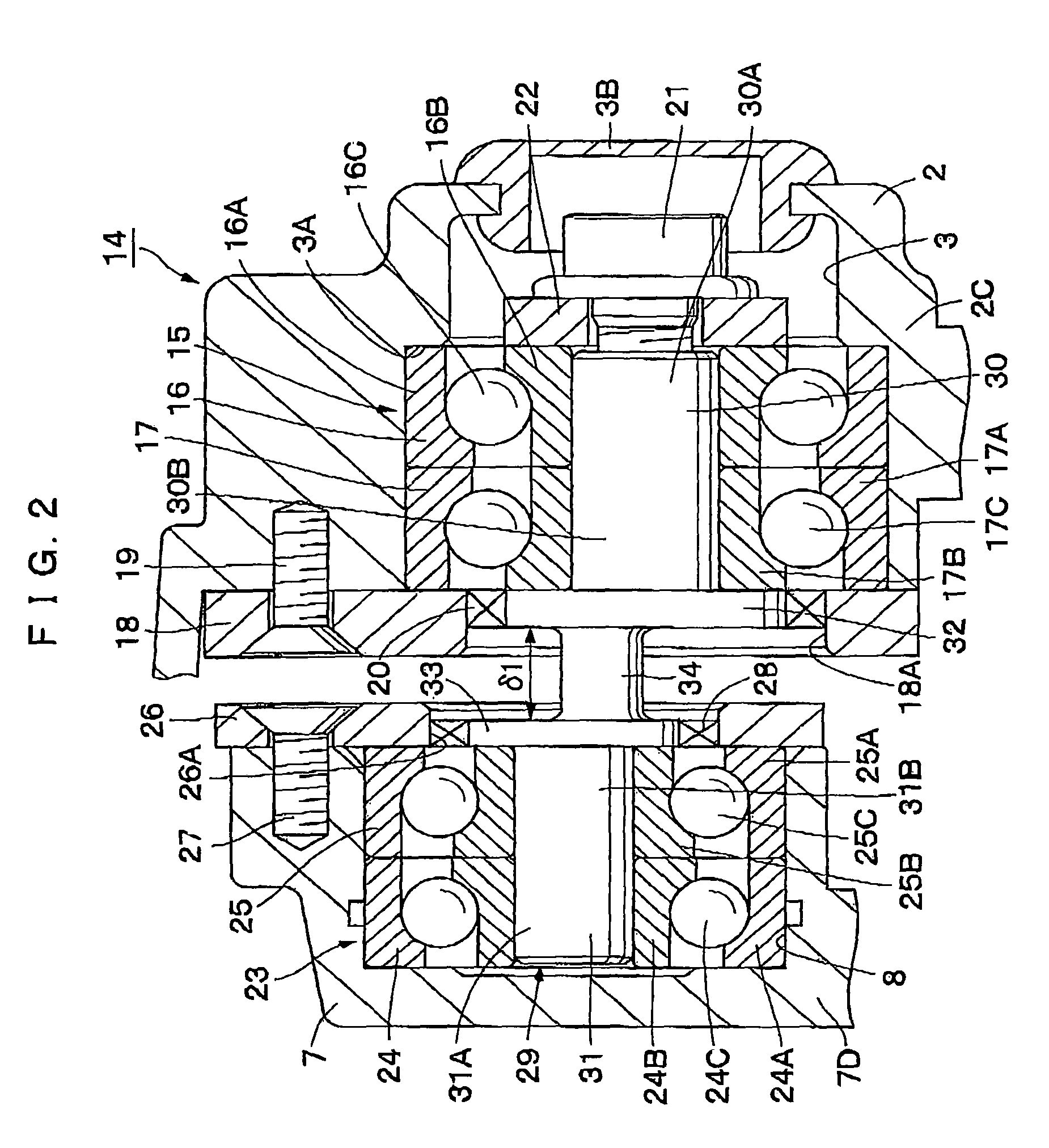
[0033]First, FIGS. 1 to 3 show the present invention. In FIG. 1, a reference numeral 1 is a scroll-type air compressor which compresses air. This scroll-type air compressor 1 generally comprises: a casing 2; a fixed scroll 4; an orbiting scroll 7; a driving shaft 10 and an auxiliary crank device 14 (details of those parts will be explained hereinafter).

[0034]A reference numeral 2 is the casing forming an outer frame of the scroll-type air compressor 1. One side of the casing 2 in its axial direction is nearly closed while the other side thereof is opened, so that the casing 2 is formed into a cylindrical body with a stepped portion. Further, the casing 2 generally comprises: a large diameter cylinder 2A; a small diameter cylinder 2B having a diameter less than the one of the large diameter cylinder 2A and being extended outside from one side of the large diameter cylinder 2A in its axial direction; and an annular portion 2C formed between the small diameter cylinder 2B and the large...

second embodiment

[0092]A reference numeral 81 is an auxiliary crank device according to the This auxiliary crank device 81 comprises: the casing-side ball bearing 15, the scroll-side ball bearing 23, a cap member 82, an auxiliary crank shaft 83, and the like.

[0093]A reference numeral 82 is a closed-end, cylindrical cap member in which to be inserted into the inner rings 24B, 25B of the scroll-side ball bearing 23. This cap member 82 comprises: a disk-like bottom portion 82A; a cylindrical portion 82B axially extended from the bottom portion 82A; a brimmed portion 82C provided on an opening side of the cylindrical portion 82B and extended outside in the radius direction. The cap member 82 is press-fitted into the inner rings 24B, 25B and rotated with the inner rings 24B, 25B in an integral manner. Further, the cylindrical portion 82B of the cap member 82 may have an outer diameter dimension D11 less than an outer diameter dimension D10 of a fixed-side shank 84 of the auxiliary crank shaft 83 later e...

third embodiment

[0118]A reference numeral 91 is an auxiliary crank device according to the This auxiliary crank device 91 comprises: the casing-side ball bearing 15; the scroll-side ball bearing 23; a cap member 92; an auxiliary crank shaft 93; and the like.

[0119]A reference numeral 92 is a closed-end, cylindrical cap member in which to be inserted into the inner rings 24B, 25B of the scroll-side ball bearing 23. This cap member 92, as the same with the cap member 82 in the second embodiment, comprises: a bottom portion 92A; a cylindrical portion 92B; and a brimmed portion 92C. Further, the interior of the cap member 92 is formed with, as the same with the small-diameter cavity 82D and the large diameter cavity 82E of the cap member 82, a stepped cavity composed of a small-diameter cavity 92D and a large-diameter cavity 92E. The cap member 92 is press-fitted into the inner rings 24B, 25B and rotated with the inner rings 24B, 25B in an integral manner.

[0120]The cap member 92 is, however, different ...


PUM


Abstract

A scroll-type fluid machine comprising: a casing; a fixed scroll; an orbiting scroll; and an auxiliary crank device in which to prevent the orbiting scroll from being rotated, wherein the auxiliary crank device comprises: a fixed-side bearing body provided on either a casing side or a fixed scroll side; an orbiting-side bearing body provided on an orbiting scroll side; and an auxiliary crank shaft in which a fixed-side shank is rotatably supported with the fixed-side bearing body, and an orbiting-side shank is rotatably supported with the orbiting-side bearing body; a tip of the fixed-side shank of the auxiliary crank shaft is fixed in a radius direction, and a tip of the orbiting-side shank of the auxiliary crank shaft is fixed in a radius direction; and a deformative portion is provided between the tip of the fixed-side shank and the tip of the orbiting-side shank of the auxiliary crank shaft.

Description

BACKGROUND OF THE INVENTION[0001]1. Field of the Invention[0002]The present invention relates to a scroll-type fluid machine suitable for a compressor for fluid such as air, a vacuum pump, an expansion device, and the like.[0003]2. Description of the Related Art[0004]In general, a scroll-type fluid machine can be categorized into a compressor compressing fluid such as air or refrigerant, a vacuum pump depressurizing an interior of a container, an expansion device expanding fluid, and the like. This type of the scroll-type fluid machine generally comprises: a casing; a fixed scroll fixed to the casing wherein a spiroid lap portion is standing on a surface of an end plate; an orbiting scroll provided with a spiroid lap portion standing on a surface of an end plate, the orbiting scroll forming a plurality of fluid chambers so as to compress or expand fluid between the fixed scroll and the orbiting scroll through orbiting motion; a driving shaft rotatably provided within the casing so a...

Claims


Application Information

Patent Timeline
Patent Type & Authority Patents(United States)
IPC IPC(8): F03C4/00F04C18/00
CPCF01C17/06F04C18/0215
Inventor KOMAI, YUJISUEFUJI, KAZUTAKAHARASHIMA, TOSHIKAZUIWANO, KIMINORISUZUKI, TOSHITSUGUKANEMOTO, YOSHIYUKI
Owner HITACHI LTD
Why Eureka
Try Eureka