Method and system of radio frequency (RF) power transmission in a wireless network

a wireless network and radio frequency technology, applied in the field of power transmission, can solve the problems of large number of nodes and adoption of wireless mesh networks

Active Publication Date: 2012-06-05
SAMSUNG ELECTRONICS CO LTD
View PDF13 Cites 14 Cited by
  • Summary
  • Abstract
  • Description
  • Claims
  • Application Information

AI Technical Summary

Benefits of technology

[0017]The control signals represent control information enabling devices (e.g., wireless stations or nodes) that include an integrated wireless power and data transmission module, to switch between a power receiving mode and a data communication mode (i.e., power mode switching). In one example star communication network, a coordinator station (or master device) is the power transmitter as well as the central controller of the communication network. Beacon frames transmitted by the coordinator are utilized by receiving devices in the network to control the timing of switching between power receiving mode and data communication mode. In a mesh network, because there is no coordinator / master device, the devices in the network are charged by data transmissions occurring in their neighborhood and / or other devices scattered in the network. Said control signals enable the receiving devices in a network to determine when to switch modes (between power receiving mode and data communication mode), and which mode to switch to. This allows the receiving devices to avoid conflict between energy reception and data communication, and to thereby avoid missing data messages from other devices.

Problems solved by technology

In such networks, the number of nodes may be very large.
One of the technical challenges for sustaining wireless mesh networks is maintaining batteries for hundreds, or even thousands, of nodes in a network.
This is an obstacle for widespread adoption of wireless mesh networks.

Method used


Image

  • Method and system of radio frequency (RF) power transmission in a wireless network
  • Method and system of radio frequency (RF) power transmission in a wireless network
  • Method and system of radio frequency (RF) power transmission in a wireless network

Examples


Embodiment Construction

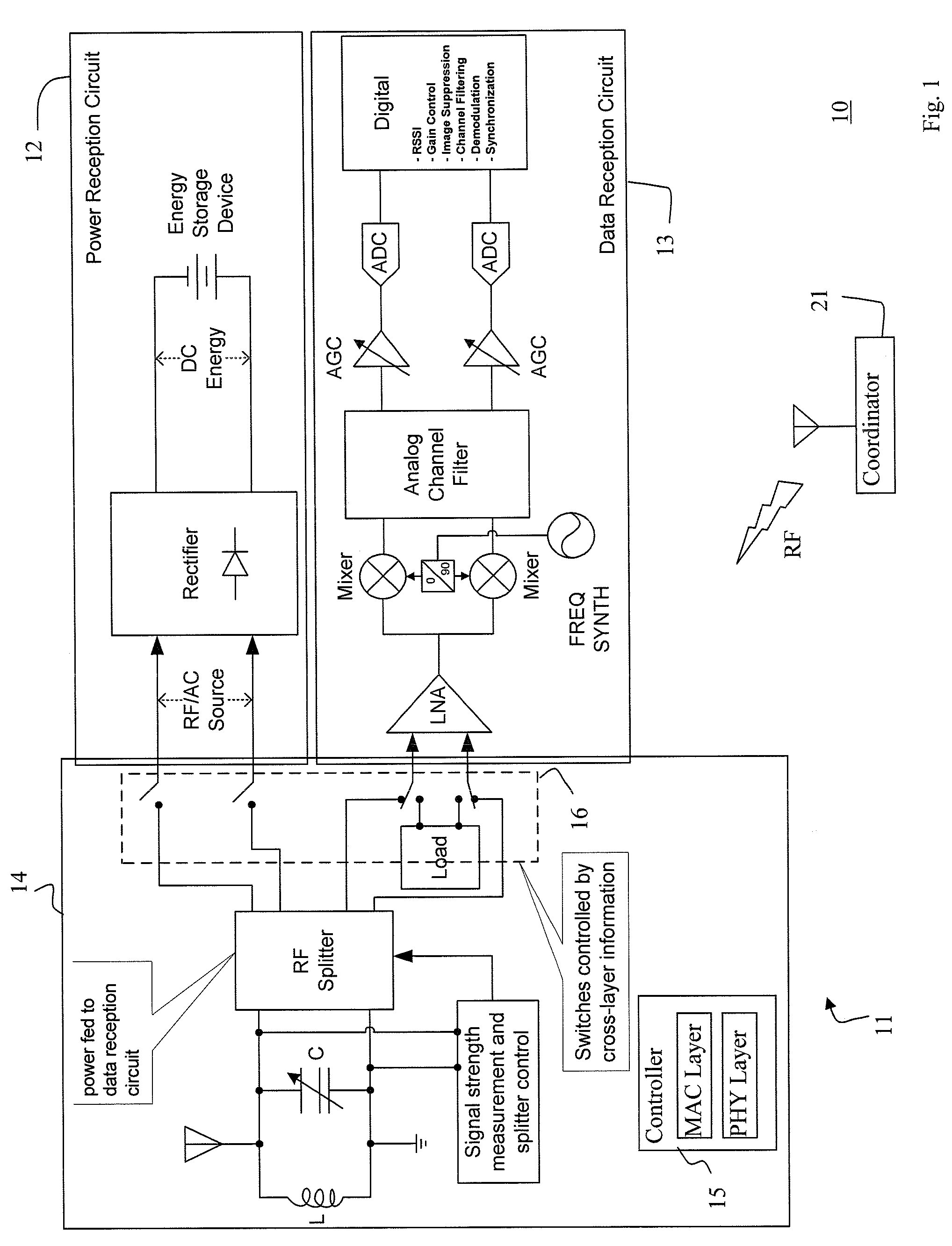
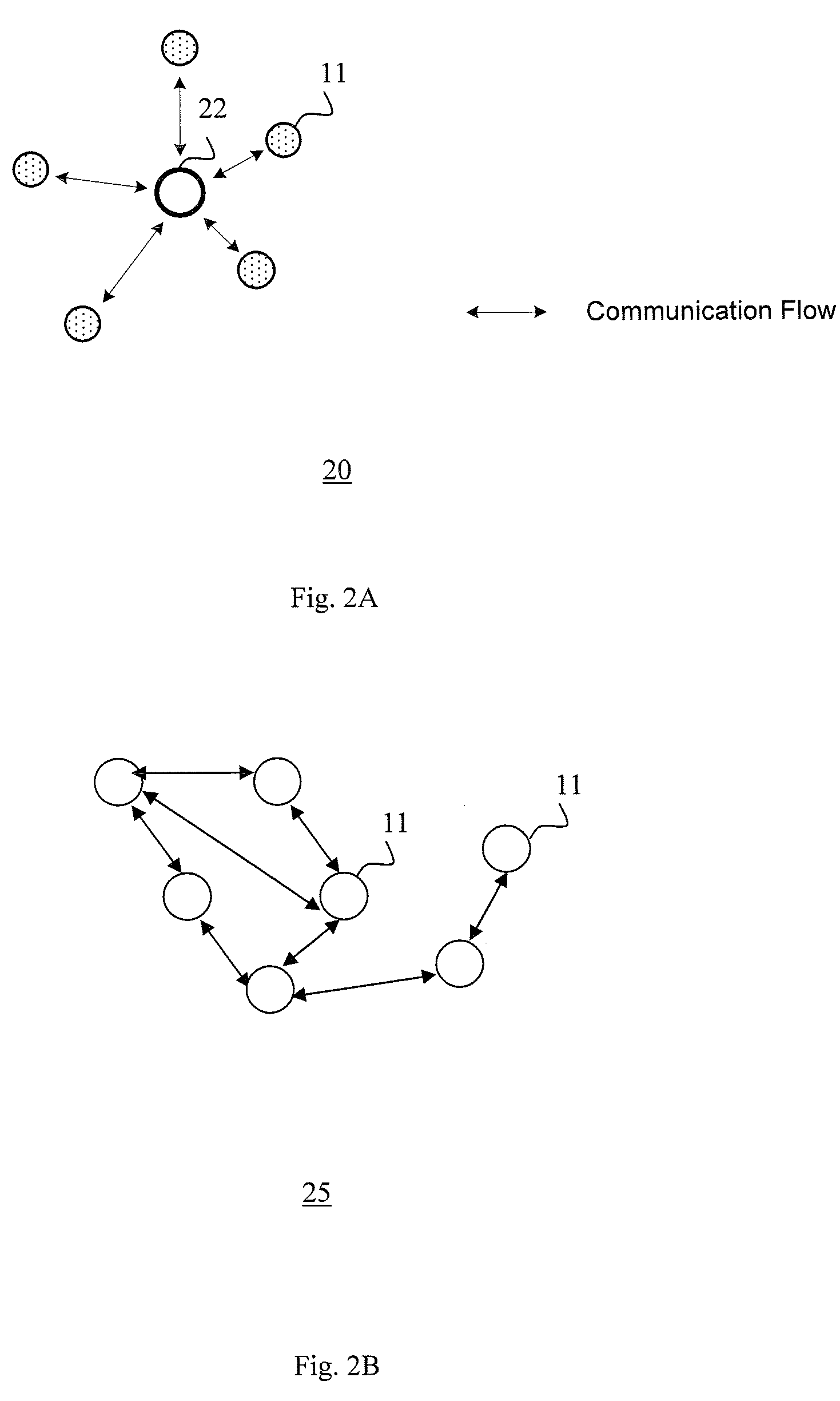
[0016]The invention provides a method and system for transmitting electrical charge to a charge storage unit of a device, and information delivery to the same device, using radio frequency (RF) radiation. One embodiment provides a process for cross-layer control of RF power transmission in an RF wireless network. The control process allows both wireless communication and power transmission using a single, common antenna. The invention provides control signals to an integrated wireless power and data transmission module. The control signals enable the integrated wireless power and data transmission module to operate in a wireless network such as a network having a star or mesh (i.e., peer-to-peer) topology.

[0017]The control signals represent control information enabling devices (e.g., wireless stations or nodes) that include an integrated wireless power and data transmission module, to switch between a power receiving mode and a data communication mode (i.e., power mode switching). I...


PUM


Abstract

A method and system of radio frequency (RF) power transmission among multiple wireless stations is provided. Control signals for switching a receiving station between a power reception mode and a data reception mode are generated. The control signals provide switching information about which of the modes to switch to, and timing of the switching. In the data reception mode, the receiving station processes an RF transmission from a sending station as a data communication. In the power reception mode the receiving station processes the RF transmission as energy radiation for powering the receiving station. One type of control signal for power mode switching is generated at the MAC layer of a receiving station and sent to the PHY layer of that station for power mode switching. Another type is RTS / CTS control signal exchanged between the sending and receiving stations.

Description

FIELD OF THE INVENTION[0001]The invention relates generally to power transmission, and in particular, to power and data transmission to the same device via radio frequency (RF) radiation.BACKGROUND OF THE INVENTION[0002]With the proliferation of mobile electronic devices, many wireless devices are necessarily powered by batteries. For example, devices in wireless local area network (WLAN) or wireless personal area network (WPAN) mesh networks are battery powered. In such networks, the number of nodes may be very large. One of the technical challenges for sustaining wireless mesh networks is maintaining batteries for hundreds, or even thousands, of nodes in a network. Current battery technology requires the battery of a wireless sensor node to be changed every several days or at most every several months. This is an obstacle for widespread adoption of wireless mesh networks.BRIEF SUMMARY OF THE INVENTION[0003]The invention provides a method and system of radio frequency (RF) power tr...

Claims


Application Information

Patent Timeline
Patent Type & Authority Patents(United States)
IPC IPC(8): H02J17/00H04B7/00
CPCH02J17/00G08C17/02H02J50/20H02J50/40H02J50/80H04B5/0037
Inventor ZHU, CHUNHUINGO, CHIU
Owner SAMSUNG ELECTRONICS CO LTD
Why Eureka
Try Eureka