Road-lane marker detection using light-based sensing technology

a technology of light-based sensing and road-lane markers, applied in the field of lane marker detection, can solve the problems of vision-based systems being susceptible to incorrectly distinguishing lane markers, vision-based systems being typically challenged, etc., and achieve the effect of reliable detection performance and fast processing speed

Inactive Publication Date: 2012-06-05
CARNEGIE MELLON UNIV +1
View PDF11 Cites 29 Cited by
  • Summary
  • Abstract
  • Description
  • Claims
  • Application Information

AI Technical Summary

Benefits of technology

[0003]An advantage of the invention provides for fast processing speeds and reliable detection performance for the lane marker in the captured LIDAR reflectivity data. The method first selects candidate regions for lane marker segments based on the reflectivity properties of the lane marker and adjacent areas. The data is then filtered and examined to determine the presence and location of the lane markers.
[0004]An embodiment contemplates a method of detecting road lane markers using a light-based sensing technology. Reflectivity data is captured using the light-based sensing device. A light intensity signal is generated based on the captured reflectivity data received by the light-based sensing device. The light intensity signal is convolved with a differential filter for generating a filter response that identifies a candidate lane marker region and ground segment regions juxtaposed on each side of the candidate lane marker region. A weighted standard deviation of data points within the identified candidate lane marker region is calculated. A weighted standard deviation of data points within the ground segment regions juxtaposed to the candidate lane marker region is calculated. An objective value is determined for the identified candidate lane marker region as a function of the weighted standard deviation of data points within the candidate lane marker region, the weighted standard deviation of data points within the ground segment regions juxtaposed to the identified candidate lane marker region, and a number of data points contained within the identified candidate lane marker region. The objective value is compared to a respective threshold for determining whether the identified candidate lane marker region is a lane marker.
[0005]An advantage of an embodiment provides for a lane marker detection system. The system includes a light-based sensing device for capturing road input data. A processor receives the captured road input data received by the light-based sensing device. The processor generates a light intensity signal based on the captured reflectivity data. The processor convolves the light intensity signal with a filter for generating a filter response for identifying a candidate lane marker region and adjacent ground segment regions. The processor determines a weighted standard deviation of data points within the identified candidate lane marker region and a weighted standard deviation of data points within the adjacent ground segments. The processor calculates an objective value for the identified candidate lane marker region as a function of the respective weighted standard deviations and a number of data points within the identified candidate lane marker region. The processor compares the objective value to a threshold for determining whether the identified candidate lane marker region is a lane marker. An output device identifies a location of the lane markers.

Problems solved by technology

The issue is that most systems utilize a vision-based system such as a camera to analyze the captured image.
Such vision-based systems are susceptible to incorrectly distinguishing lane markers due to the lighting conditions, shadows from trees and buildings, or poorly painted or warn lane markers.
Furthermore, vision based systems are typically challenged by certain situations such sharp curves in the road.

Method used


Image

  • Road-lane marker detection using light-based sensing technology
  • Road-lane marker detection using light-based sensing technology
  • Road-lane marker detection using light-based sensing technology

Examples


Embodiment Construction

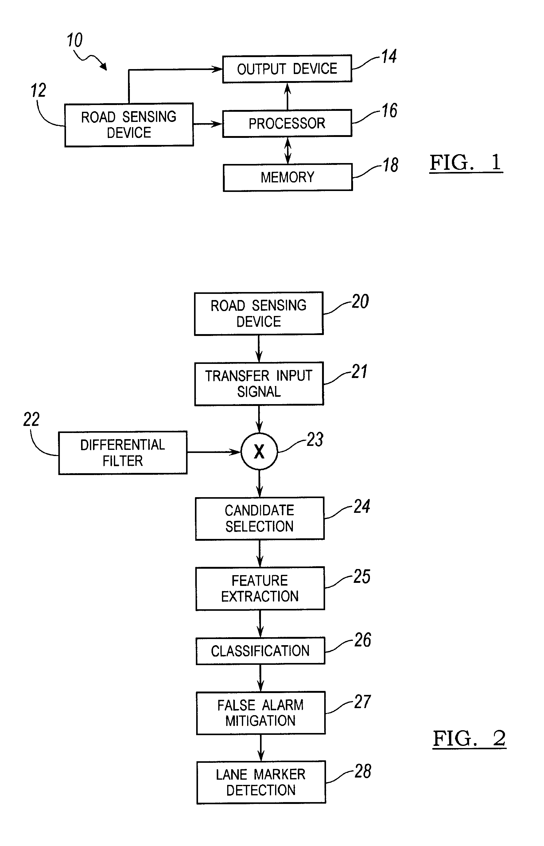
[0017]There is shown in FIG. 1 a light-based sensing system 10 for detecting lane markers in a vehicle road. The light-based sensing system 10 is used to detect road lane markers in the road of the driven vehicle. The light-based sensing system 10 is used in an autonomous steering system for road lane marker detection. Alternatively, the light-based sensing system 10 may be used for driver awareness for a vehicle driven by a driver to enhance visibility during the daytime or nighttime when road lane marker visibility is poor or during other instances when visibility enhancement is warranted.

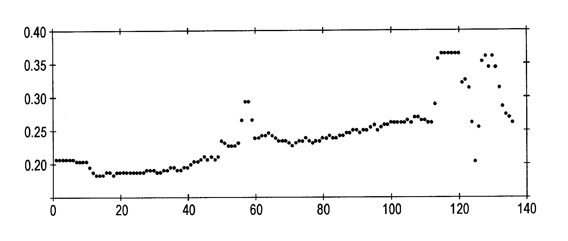
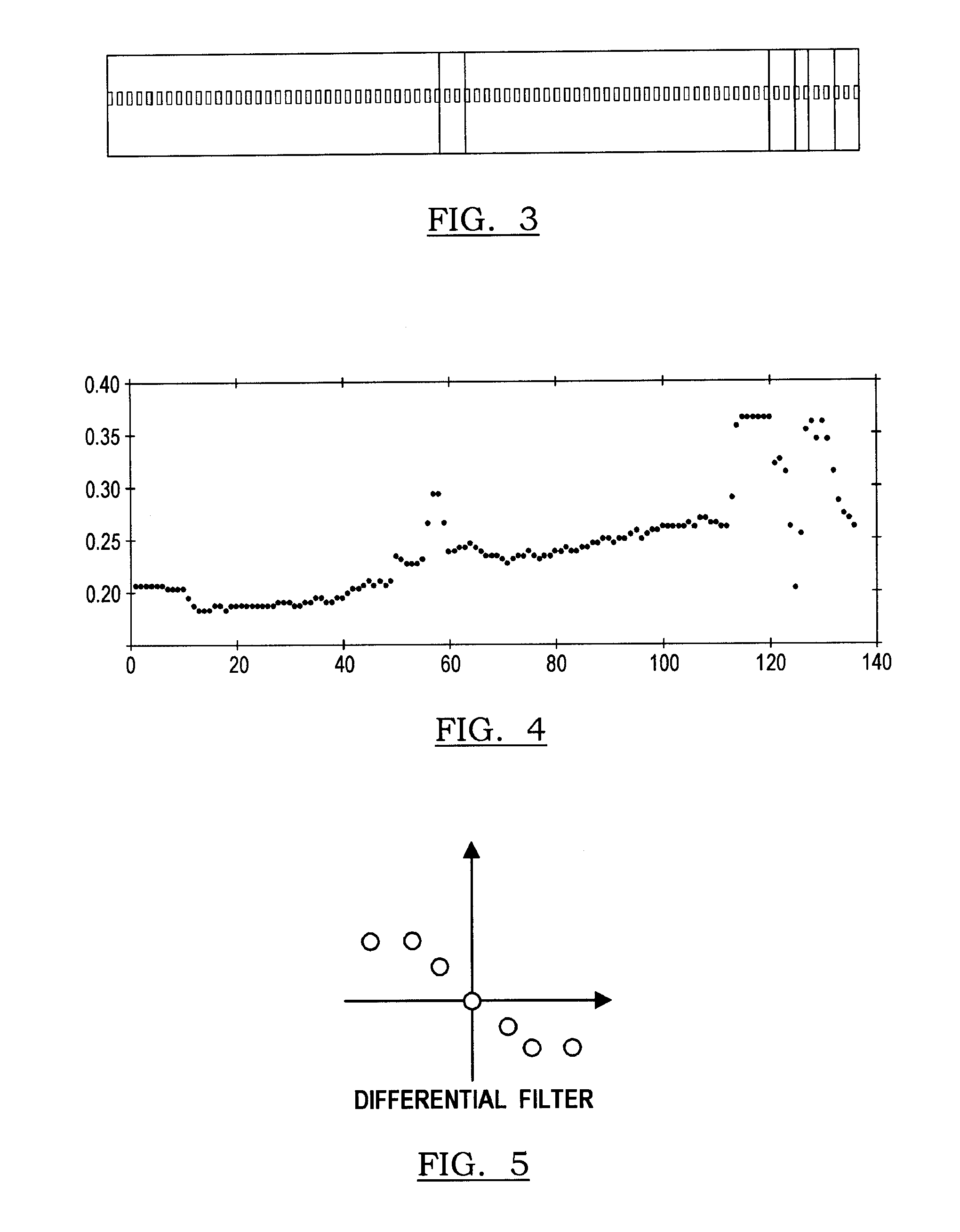
[0018]The light-based sensing system 10 includes a road sensing device 12 including, but not limited to, a Light Detection and Ranging (LIDAR) sensing device or a camera. The LIDAR device measures the properties of scattered light to determine certain characteristics such as reflectivity values for differentiating road lane markings from ground segments (i.e., non-lane markings).

[0019]The light-b...


PUM


Abstract

A method is provided for detecting road lane markers using a light-based sensing device. Reflectivity data is captured using the light-based sensing device. A light intensity signal is generated based on the captured reflectivity data. The light intensity signal is convolved with a differential filter for generating a filter response that identifies a candidate lane marker region and ground segment regions juxtaposed on each side of the candidate lane marker region. A weighted standard deviation of the data points within the identified candidate lane marker region and weighted standard deviation of the data points within the ground segment regions are calculated. An objective value is determined as a function of the respective weighted standard deviations. The objective value is compared to a respective threshold for determining whether the identified candidate lane marker region is a lane marker.

Description

BACKGROUND OF INVENTION[0001]An embodiment relates generally to lane marker detection of a vehicle road using light-based sensing technology.[0002]Lane marker detection is used either to alert a vehicle driver of the presence of road lane markers in the vehicle driving path, or to provide the feasible driving area constraint for route planning in autonomous driving. The issue is that most systems utilize a vision-based system such as a camera to analyze the captured image. Such vision-based systems are susceptible to incorrectly distinguishing lane markers due to the lighting conditions, shadows from trees and buildings, or poorly painted or warn lane markers. Furthermore, vision based systems are typically challenged by certain situations such sharp curves in the road.SUMMARY OF INVENTION[0003]An advantage of the invention provides for fast processing speeds and reliable detection performance for the lane marker in the captured LIDAR reflectivity data. The method first selects cand...

Claims


Application Information

Patent Timeline
Patent Type & Authority Patents(United States)
IPC IPC(8): G06K9/00
CPCG06K9/00798G06V20/588
Inventor ZHANG, WENDESADEKAR, VARSHAURMSON, CHRISTOPHER PAUL
Owner CARNEGIE MELLON UNIV
Why Eureka
Try Eureka