Hydraulic tensioner

a technology of hydraulic tensioner and tensioner rod, which is applied in the direction of belt/chain/gearing, mechanical equipment, belt/chain/gearing, etc., can solve the problems of increasing oil pressure in the hydraulic chamber, increasing friction of the chain, and excessive reaction force acting on the chain

Active Publication Date: 2012-06-12
BORG WARNER MORSE TEC JAPAN KK
View PDF21 Cites 20 Cited by
  • Summary
  • Abstract
  • Description
  • Claims
  • Application Information

AI Technical Summary

Benefits of technology

[0014]According to the present invention, as above-mentioned, since the entire opening areas of the inner and outer relief apertures providing a connection between the plunger bore and the outside of the housing vary at least at two stages in accordance with the travel of the spool, oil pressure in the hydraulic chamber formed between the plunger and the plunger bore can be changed at least at two stages. Thereby, under various engine operating conditions, force from the plunger to the chain can be regulated and an increase in chain friction can thus be prevented.
[0016]In such a way, since both the inner and outer relief apertures are closed by the spool at idle, oil pressure in the hydraulic chamber can be maintained at a relatively high state. Therefore, by supplying high pressure oil into the hydraulic chamber at idle, the plunger can be securely pressed against the chain and noise due to chattering of the plunger can thus be prevented from occurring. Also, since the inner relief aperture and one of the outer relief apertures are open during normal operation, oil pressure in the hydraulic chamber can be maintained at a level lower than the oil pressure at idle. Thereby, chain friction can be decreased during normal operation. Further, since both the two outer relief apertures and the inner relief aperture are open during engine operation causing chain resonance, oil pressure in the hydraulic chamber can be maintained at a level lower than the oil pressure at the normal operation. Thereby, chain friction can be decreased during chain resonance.
[0020]In this case, the amount of oil discharged from the tensioner during travel of the spool will not be increased abruptly by the difference in level between the land and the small diameter portion of the spool. In contrast, the tapered portion between the land and the small diameter portion of the spool allows the amount of oil discharged from the tensioner to vary smoothly.

Problems solved by technology

In such a hydraulic tensioner, when the tension in the chain has increased due to resonance of a chain span and the chain imparts an excessive force to the plunger, oil pressure in the hydraulic chamber increases and an excessive reaction force acts upon the chain from the plunger.
As a result, friction of the chain may increase.
However, the prior-art hydraulic tensioner is constructed such that the pressure relief valve opens only when the pressure in the hydraulic chamber has exceeded the predetermined level and it is thus difficult to correspond to the various operating conditions of the engine.
For example, in the case of a tensioner where a relatively high oil pressure is supplied in order to control chain motions at idle of the engine, pressure in the hydraulic chamber becomes higher than the expected value at the normal operating conditions of the engine and chain frictions thus increase.
However, in this case, at the time of resonance of a chain span, pressure relief of the hydraulic chamber cannot be fully carried out, thus causing a problem of an increase of chain friction due to excessive tension of the chain span.
Also, in the case of a tensioner where a relief valve is set to open only at the time of resonance of a chain span, pressure of the hydraulic chamber cannot be maintained at an appropriate value both at idle and at normal operating conditions.
Similarly, a problem of an increase of chain friction occurs.
An increase of chain friction incurs a decrease of fuel efficiency of an engine, which is contrary to the demand for improved fuel efficiency in the automotive industry that has reflected recent environmental issues.

Method used


Image

  • Hydraulic tensioner
  • Hydraulic tensioner
  • Hydraulic tensioner

Examples


Embodiment Construction

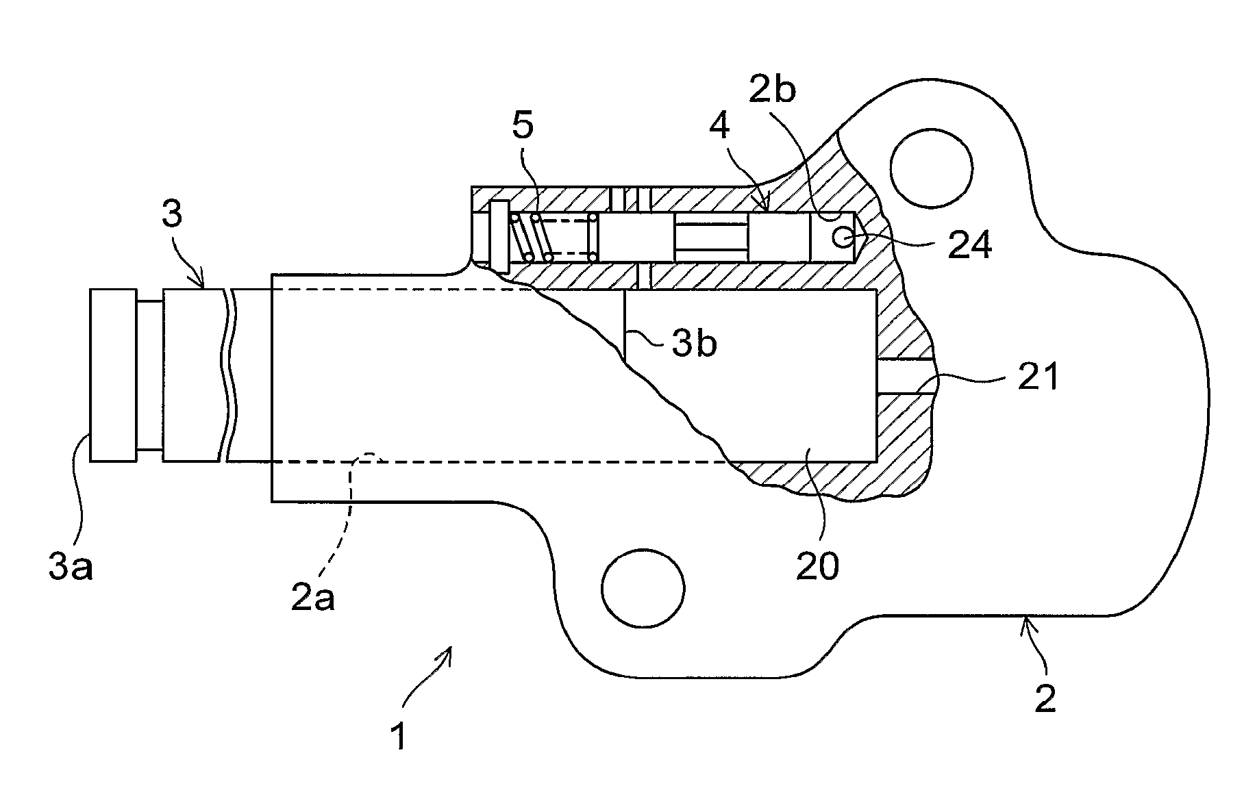
[0034]FIGS. 1 to 5 show a hydraulic tensioner according to a first embodiment of the present invention. As shown in FIG. 1, a hydraulic tensioner 1 includes a housing 2, a plunger 3 slidably received in a plunger bore 2a that is formed in the housing 2, and that extends in the axial direction to an opening end, and a spool 4 slidably received in a spool bore 2b that is formed in the housing 2.

[0035]In the plunger bore 2a, a hydraulic chamber 20 is defined by the inner wall surface of the plunger bore 2a and the rear end surface 3b of the plunger 3. An oil passage 21 is formed in the housing 2 to introduce oil pressure from the source of pressurized oil (e.g. oil pump, not shown) into the hydraulic chamber 20. The distal end surface 3a of the plunger 3 is adapted to exert a press onto the chain (not shown) via a tensioner arm (also not shown). In the example shown in FIG. 1, the spool bore 2b extends parallel to the plunger bore 2a.

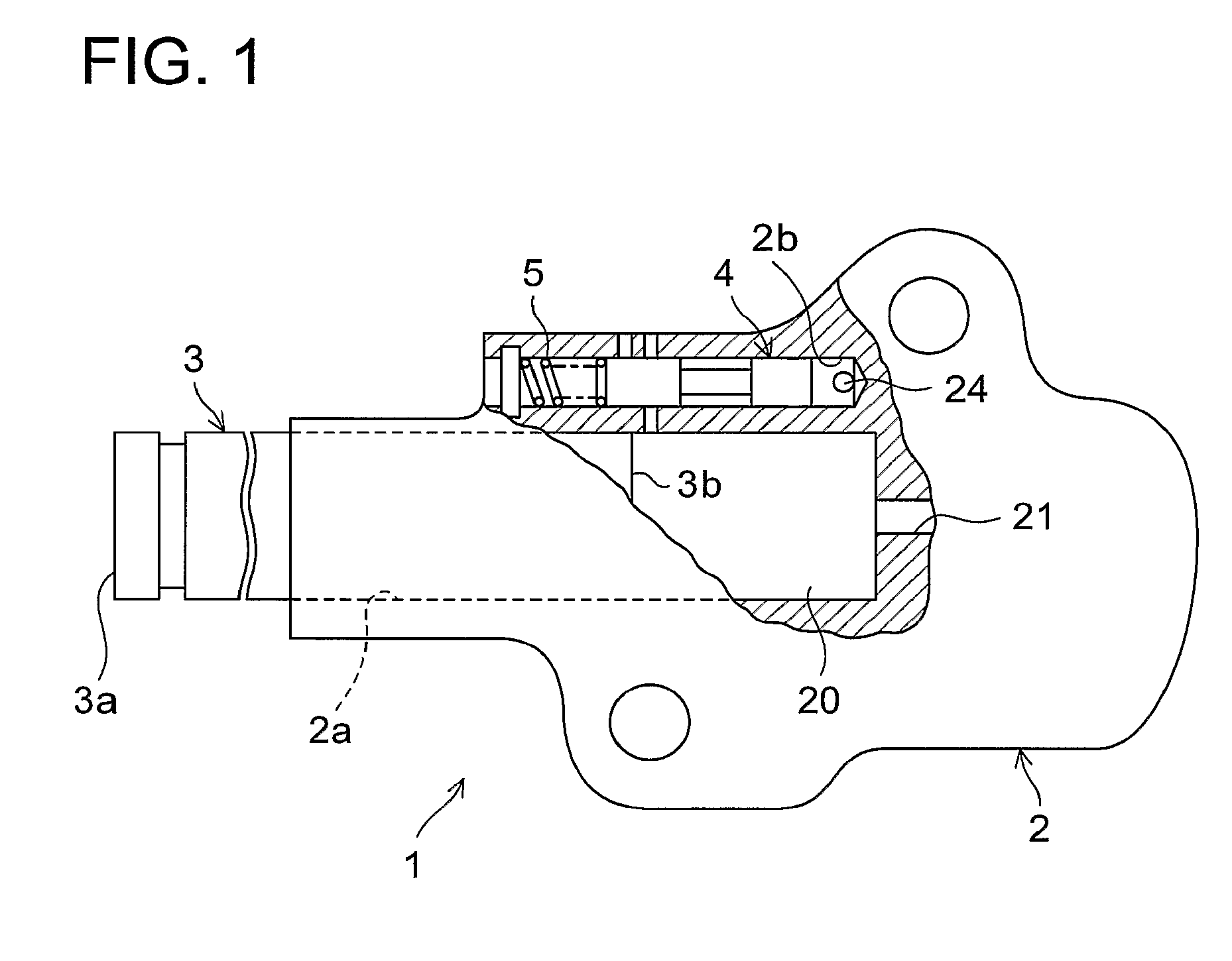
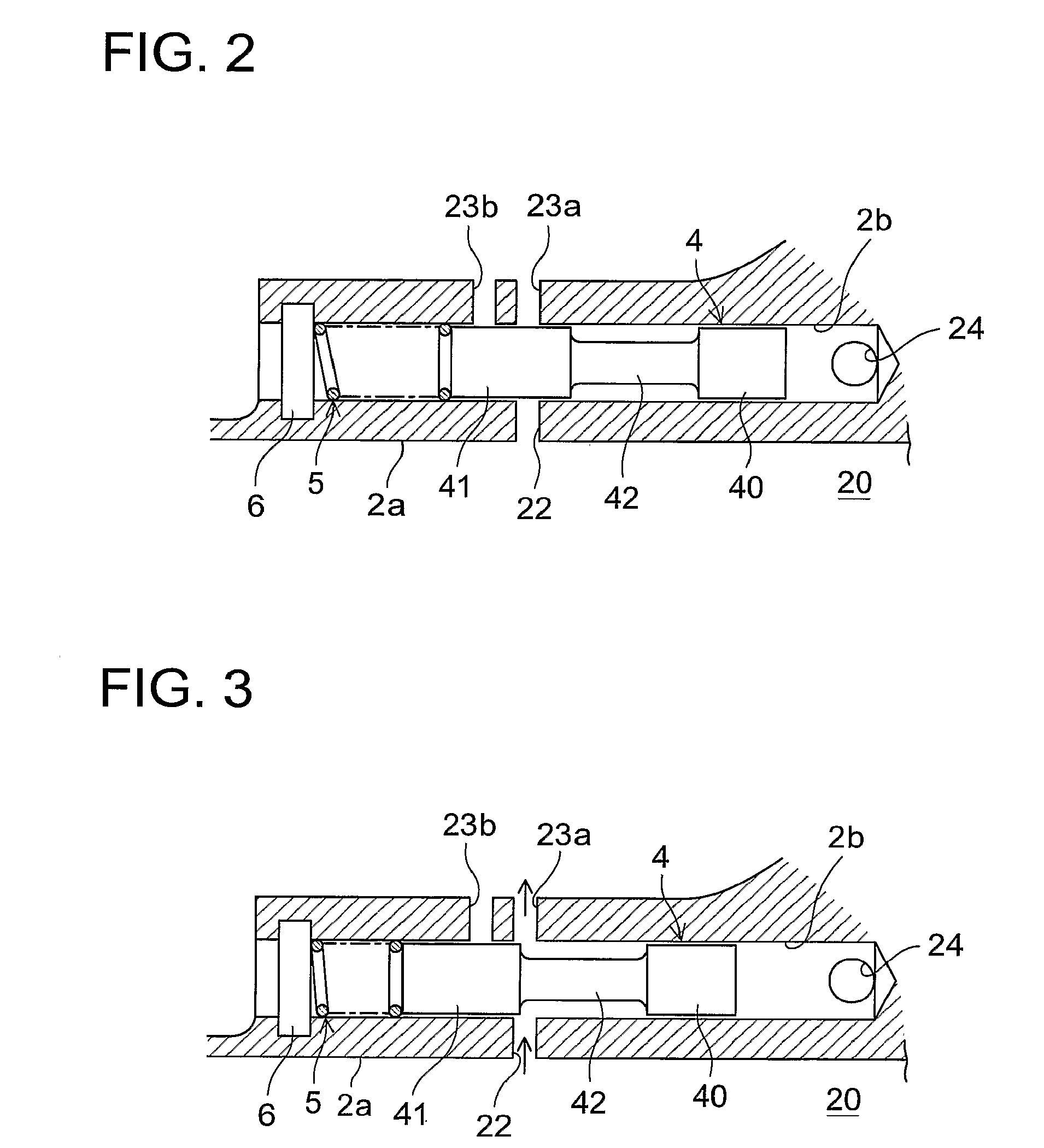
[0036]As shown in FIG. 2, the housing 2 has an inne...


PUM


Abstract

The present invention is directed to varying the oil pressure in the chamber of a hydraulic tensioner at multi-stages and preventing an increase of the chain friction at various driving conditions. A hydraulic tensioner (1) includes a housing (2) that has a plunger bore (2a) to slidably receive the plunger (3) and a spool bore (2b) to slidably receive the spool (4). The housing (2) further has an inner relief aperture (22) to provide a connection between the plunger bore and the spool bore and outside relief apertures (23a, 23b) to provide a connection between the spool bore and the outside of the housing. The entire opening areas of the inside and outside relief apertures (22, 23a, 23b) provide a connection between the plunger bore and the outside of the housing through the spool bore (2b) and vary at least at two stages in accordance with the travel of the spool (4).

Description

TECHNICAL FIELD[0001]The present invention relates to a hydraulic tensioner having a pressure relief valve that can vary the hydraulic pressure of the chamber at multi-stages.BACKGROUND ART[0002]Generally, in timing chains in use for driving valve actuating devices for internal combustion engines, cam shaft chains for drivingly connecting the cam shafts, and balancer chains, hydraulic tensioners have been used on the slack sides of the chains in order to take up slacks of the chains that occur during operation of the chains and to generate tension in the chains.[0003]A hydraulic tensioner of prior art typically includes a housing, and a plunger that is slidably received in the plunger bore formed in the housing. Oil pressure from the external source of pressurized fluid is supplied to the hydraulic chamber that is defined by the inner wall surfaces of the piston bore and the rear end surface of the piston.[0004]In such a hydraulic tensioner, when the tension in the chain has increas...

Claims


Application Information

Patent Timeline
Patent Type & Authority Patents(United States)
IPC IPC(8): F16H7/22
CPCF16H7/0848F16H2007/0806F16H2007/0859F16H2007/0814F16H2007/0812F16H7/08
Inventor MISHIMA, KUNIHIKO
Owner BORG WARNER MORSE TEC JAPAN KK
Why Eureka
Try Eureka