Vein navigation device

a navigation device and vein technology, applied in the field of vein navigation devices, can solve the problems of hammer cannulation procedures, missing the vessel, extra vascular hemorrhaging, etc., and achieve the effects of maximizing blood absorption, best contrast, and illuminating subcutaneous structures

Inactive Publication Date: 2012-06-12
NOVARIX
View PDF48 Cites 67 Cited by
  • Summary
  • Abstract
  • Description
  • Claims
  • Application Information

AI Technical Summary

Benefits of technology

[0025]The benefit of adapting the imaging device to be placed upon the recipient is that the person or persons administering a medical treatment have both hands free to do so. Furthermore the administering person is free from donning heavy and unhandy headgear which inhibits free sight and restricts the practitioner in his / hers whereabouts. Moreover, the advantage of the present invention is free mobility of the recipient and an easy reestablishment of the system in case the device has been moved, the recipient's skin or subcutaneous structure has moved or other similar scenarios. A further advantage of many of the embodiments of the invention such as the embodiment comprising hinged flaps of flexible material wherein the light emitting sources of the device are embedded is that optimal contact is ensured between the device and the recipient. This facilitates the imaging of the subcutaneous structures.
[0026]The recipient upon which the device can be adapted to be placed can be any living being, preferably an animal such as a mammal, and most preferably a human being. The device may be used on any part of the recipients' anatomy such as the legs, head, body or arms.Light Sources
[0027]The present invention will comprise at least one light emitting source for the purpose of illuminating subcutaneous structures. The governing principle of the invention is the particular absorptive qualities of various subcutaneous elements, especially the absorbance by blood of specific spectral wavelengths.
[0028]It is an aspect of the present invention to provide illumination for the visualization of a selected area of body surface, hereunder lying tissue and subcutaneous structures. This can be done in a trans-illuminating mode or a reflective mode. In one embodiment of the present invention the mode of illumination is a trans-illuminating mode. In an alternative embodiment the mode is a reflective mode.
[0029]The at least one light source preferably emits light of a wavelength between 550 and 1600 nm. This spectrum includes both visible and infrared (IR) light; and sources capable of emitting either or both, singularly or combined, are provided for in an embodiment of the present invention. The visible light is preferably yellow light of a wavelength between 550 to 580 nm or 560 to 575 nm, orange light of a wavelength between 580 to 630 nm or 585 to 610 nm, red light of a wavelength between 630 to 700 nm or 640 to 665 nm. The infrared light may be near-infrared or infrared light of wavelengths between 700 and 1600 nm or more. This includes light of any wavelength therein and in any interval therein such as light of wavelengths between, but not limited to: 700 and 800 nm, 800 and 900 nm, 900 and 1000 nm, 1000 and 1100 nm, 1100 and 1200 nm, 1200 and 1300 nm, 1300 and 1400 nm, 1400 and 1500 nm, 1500 and 1600 nm, or more. Most preferably the infrared light is of a wavelength between 800 and 900 nm, such as between 810 and 890 nm, 820 and 880 nm, 830 and 870 nm, 840 and 860 nm, 845 and 855 nm or such as between 820 and 840 nm, 825 and 835 nm, such as 830 nm or 850 nm.
[0030]Preferably, the invention comprises a combination of light sources emitting yellow (550-580 nm), orange (580-630 nm), and red (630-700 nm) light. This combination provides wavelengths that are both maximally absorbed by blood and most illuminating, giving the best contrast between blood filled structures and surrounding tissue. More preferably the invention further comprises an infrared light (700 to 1000 nm) for added in light penetration through tissue.

Problems solved by technology

Most commonly the localization is done visually or by palpitating the selected area, but this can be hampered if the recipient of the medical treatment has small, deep-lying vessels, is obese, is an infant, is anaemic, has a dark skin complexion, experiences vein contraction due to stress or suffers from burns, blood loss, dehydration or varicose veins.
Vein wall thickening or scar tissue due to repeated treatment with venous access devices may also hamper cannulation procedures.
Missing the vessel during injection can be unpleasant as this requires repeated stabbing, but can also have serious consequences such as extra vascular hemorrhaging if the vessel is punctured or tissue toxicity, if for example injecting chemotherapeutic agents.
This is unpractical and limits the mobility of the operator of the device.
Again, the requirement of eyewear is unpractical, and the use of a stand limits the flexibility and speed of the use of the device.

Method used


Image

  • Vein navigation device
  • Vein navigation device
  • Vein navigation device

Examples


Embodiment Construction

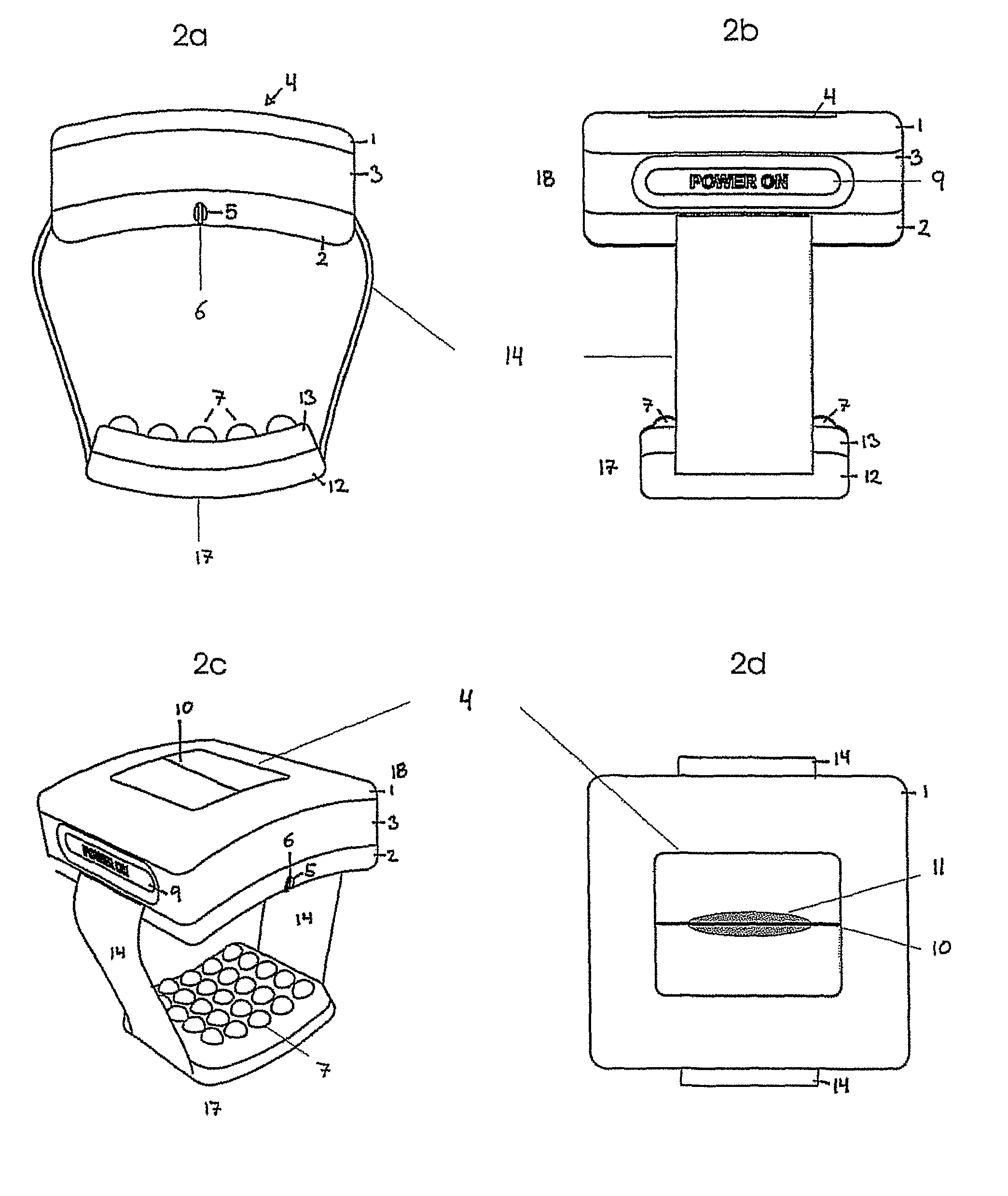
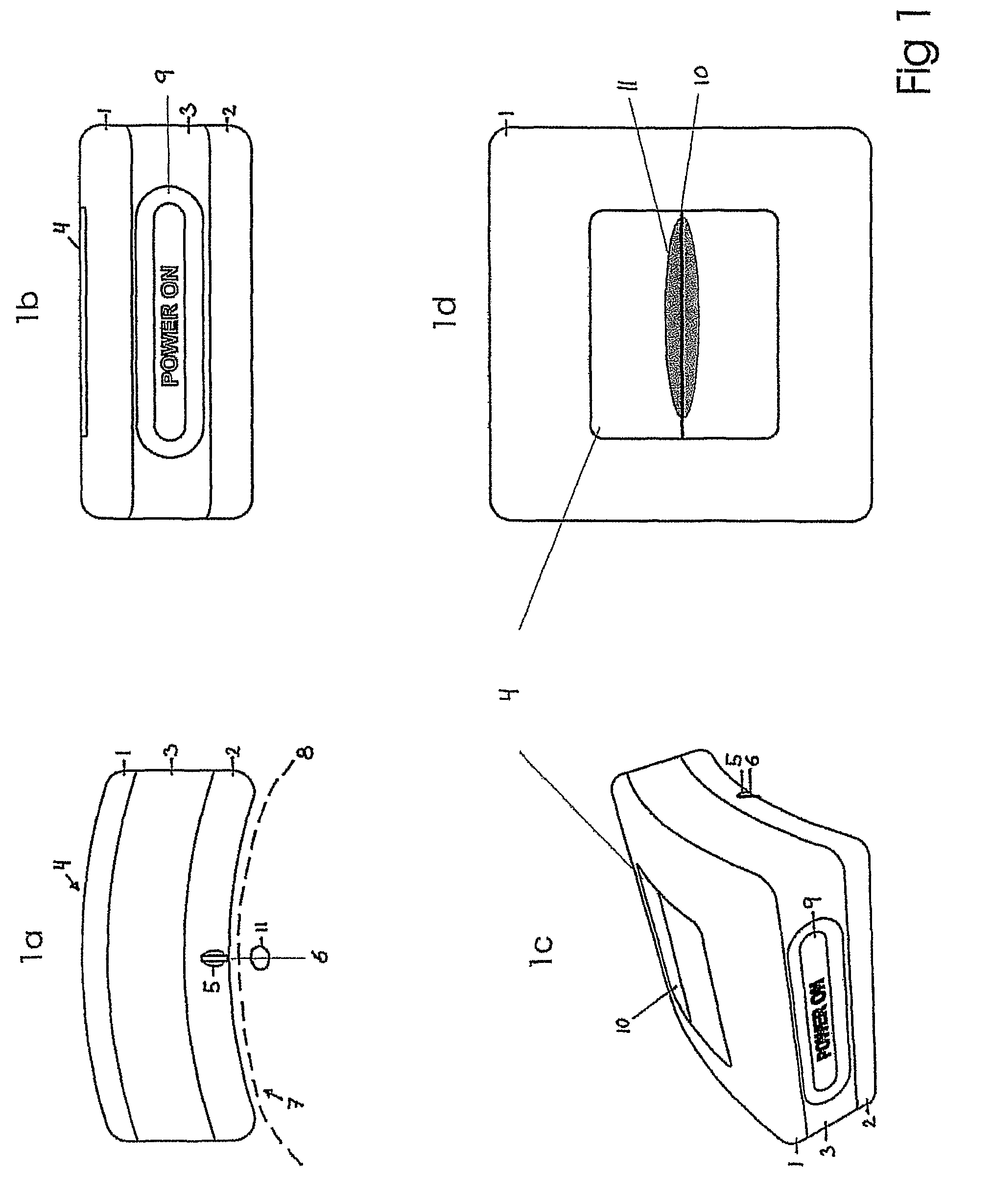
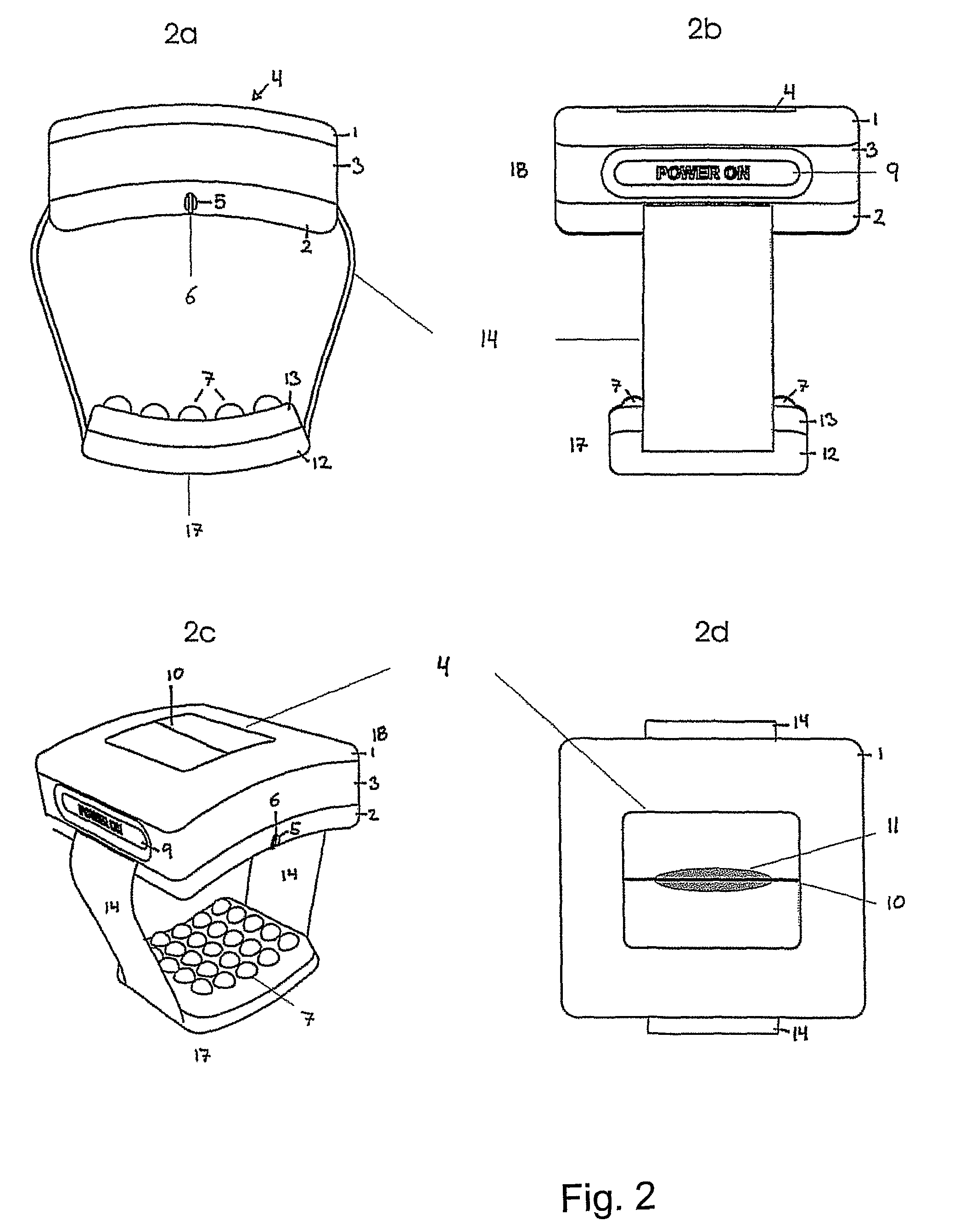
[0019]The present invention relates to a device and use of same for real time visualization of subcutaneous structures for the purpose of facilitating the insertion of medical instruments e.g. hypodermic needles, into said subcutaneous structures. The invention comprises a light emitting source, a camera and a display and is adapted to be placed upon a recipient of a medical treatment.

Adaptation to Recipient

[0020]The invention has been adapted to be placed upon the recipient in several ways. Firstly, the device is small and lightweight and therefore does not cause undue strain upon the recipient. Secondly, a fastening means can be used in conjunction with the device. Thirdly, the device itself can be shaped to fit a certain anatomical part e.g. an arm or it can be flexible in its form.

[0021]The size of the device is less than 1000 cm3. Preferably the device will be smaller than 500 cm3, 400 cm3 or 350 cm3, more preferably smaller than 300 cm3, 250 cm3, 180 cm3 or 125 cm3, most prefe...


PUM


Abstract

The present invention relates to an imaging device designed with the intent of visualizing subcutaneous structures within an organism. Visualization of subcutaneous structures will increase the speed and accuracy with which medical treatments requiring insertion of instruments into these structures can be performed. Especially fluid insertions into or extractions from an organism will be facilitated as the device is adapted to be placed upon the organism in a manner giving continued full mobility for the recipient and operator of the device.

Description

[0001]All patent and non-patent references cited in the application, or in the present application, are also hereby incorporated by reference in their entirety.FIELD OF INVENTION[0002]The present invention relates to an imaging device and procedures for use of same for non-invasive visualization of subcutaneous structures within an organism. Visualization of subcutaneous structures will increase the speed and accuracy with which medical treatments requiring insertion of instruments into these structures can be performed. Especially fluid insertions into or extractions from an organism will be facilitated as the device is adapted to be placed upon the organism in a manner giving continued full mobility for the recipient and operator of the device.BACKGROUND OF INVENTION[0003]Several medical procedures necessitate puncture of subcutaneous blood vessels and therefore require the precise localization of these. Most commonly the localization is done visually or by palpitating the selecte...

Claims


Application Information

Patent Timeline
Patent Type & Authority Patents(United States)
IPC IPC(8): H04N7/18
CPCA61B5/0059A61B5/489A61M5/427A61B5/681
Inventor KAGENOW, LISETHING, MORTEN
Owner NOVARIX
Why Eureka
Try Eureka