Two-stage light gas gun

a gas gun and two-stage technology, applied in the direction of weapons, missile propulsion, weapon components, etc., can solve the problems of significant difficulty in procuring a permit, limiting the speed of a projectile coming from a gun, and the use of explosives, so as to achieve a greater cross-sectional area and small cross-sectional area

Active Publication Date: 2012-06-19
FUHRMAN MICHAEL L
View PDF32 Cites 13 Cited by
  • Summary
  • Abstract
  • Description
  • Claims
  • Application Information

AI Technical Summary

Benefits of technology

[0008]The present disclosure addresses the deficiencies of current designs by providing a light gas gun that is capable of operating without explosive charges and which discharges the projectile in a predictable manner to achieve a specific performance.
[0009]One aspect of the present disclosure provides a system for accelerating a projectile using a light gas that provides hydraulic oil at high pressures to produce a propulsive force. This propulsive force is provided without the use of explosives and is supplied to a light gas gun having at least one piston. The light gas is preferably helium, but may also be another light gas such as hydrogen. The light gas gun may, for example, be configured with a first piston and a second piston, a hydraulic fluid residing between the two, the second piston having a smaller cross-sectional area when compared with the first piston, wherein the second piston is used to compress a light gas behind a rupture disk. The system also includes a light gas source for supplying the light gas to the light gas gun for each round fired. The rupture disk is placed between the light gas and the projectile, which is located at the end of a barrel closest to the breech. A reducing cone may be used to transition the flow of the light gas into the barrel.
[0010]Another aspect of the present disclosure provides a light gas gun having a pneumatic piston residing in a breech chamber for compressing a light gas; a rupture disk for retaining the light gas within the breech chamber until the light gas reaches a predetermined volume; a punch formed on a leading face of the pneumatic piston for puncturing the rupture disk when the light g

Problems solved by technology

One limiting factor on the speed of a projectile coming from a gun is the speed of sound in the working fluid.
One limitation of present designs is the use of explosives, which is the exclusive source of propulsive force in the prior art designs.
Because a light gas gun may be used only occasionally in a single location, the process of procuring a per

Method used


Image

  • Two-stage light gas gun
  • Two-stage light gas gun
  • Two-stage light gas gun

Examples


Embodiment Construction

[0019]In the following description, reference is made to the accompanying drawings, which form a part hereof, and in which is shown, by way of illustration, various embodiments of the present disclosure. It is understood that other embodiments may be utilized and changes may be made without departing from the scope of the present invention.

[0020]The present disclosure provides a two stage light gas gun that produces significantly higher power output when compared with a conventional, explosive-charged gun of equal size. The light gas gun of the present disclosure will have a variable power output which may be chosen to for a specific use or application. The increased power may be attributed to several stages of power increases derived from mechanical advantages gained by utilizing hydraulic and pneumatic principles.

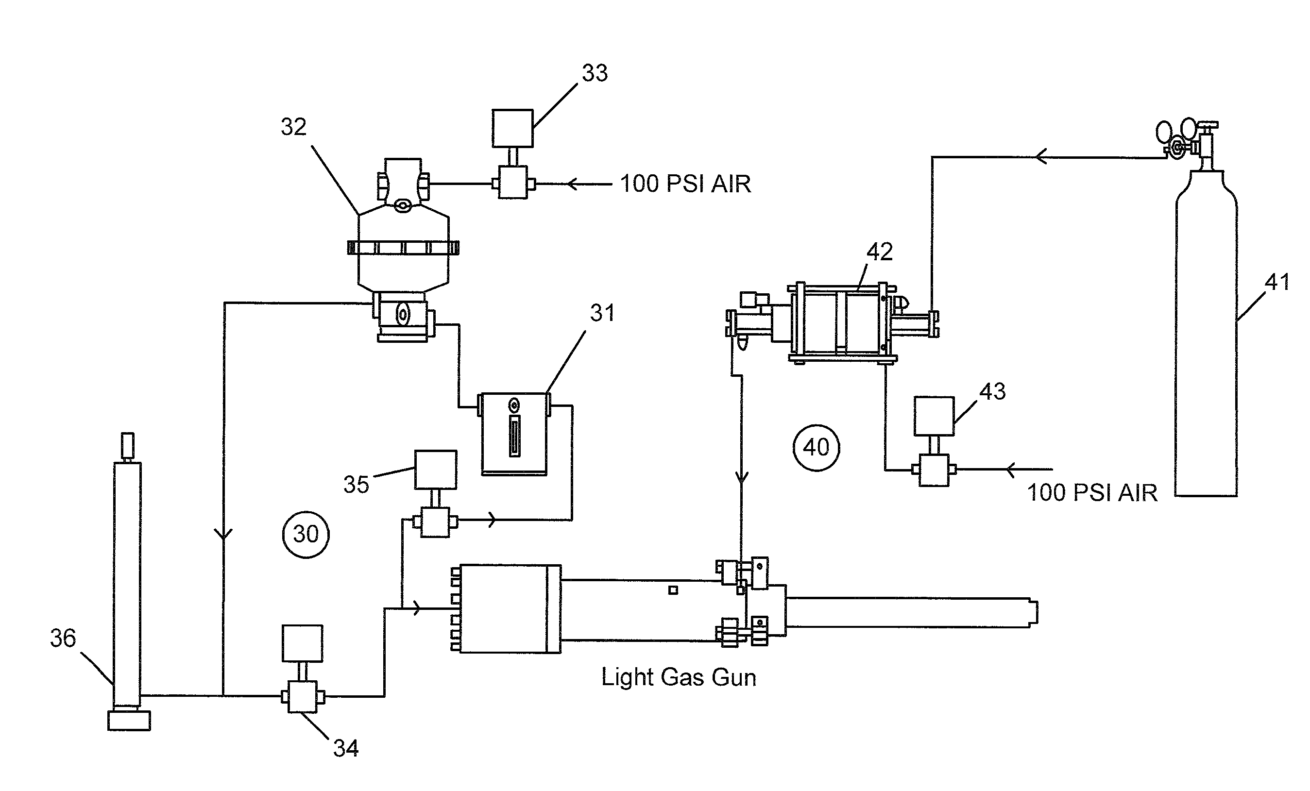
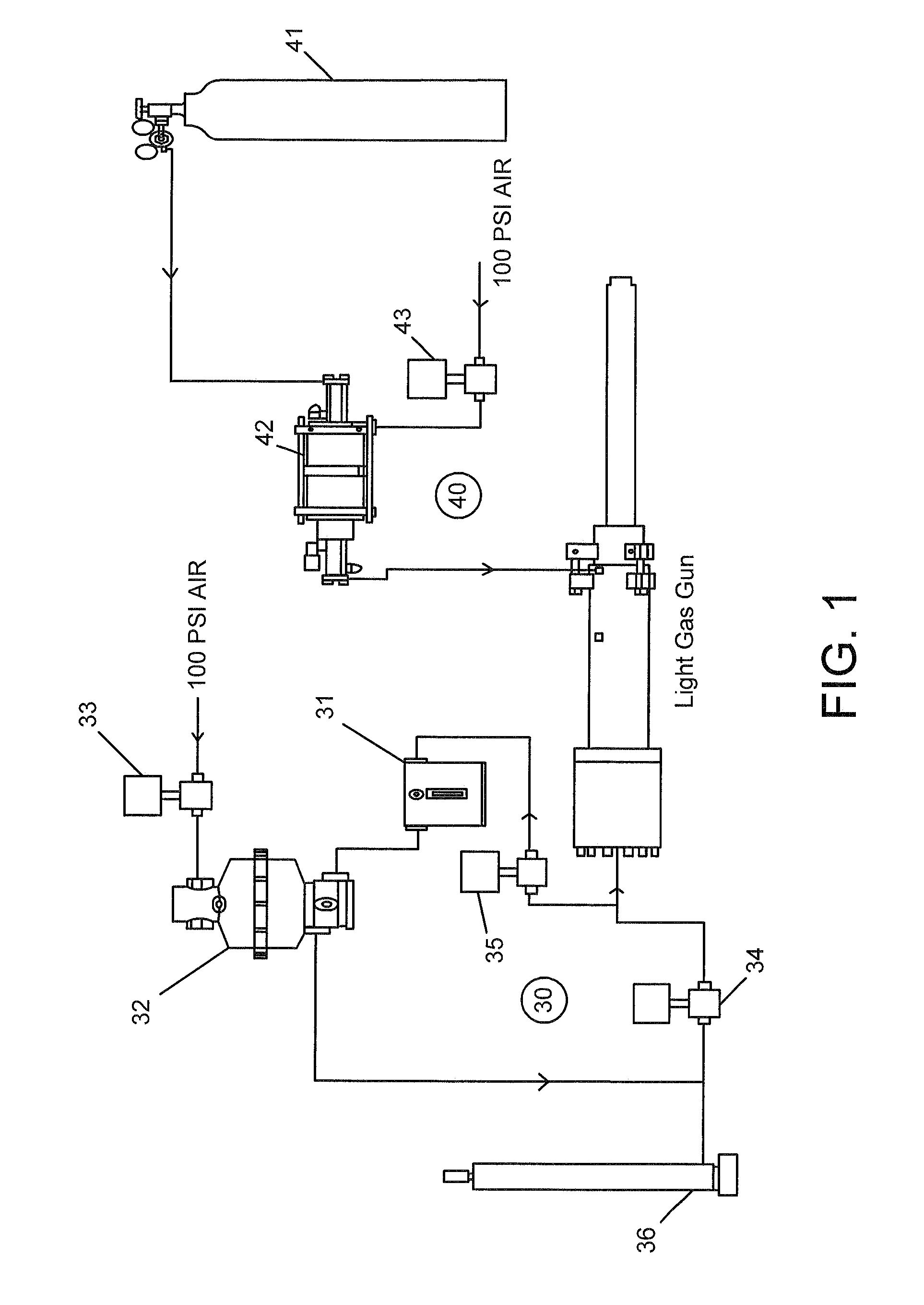
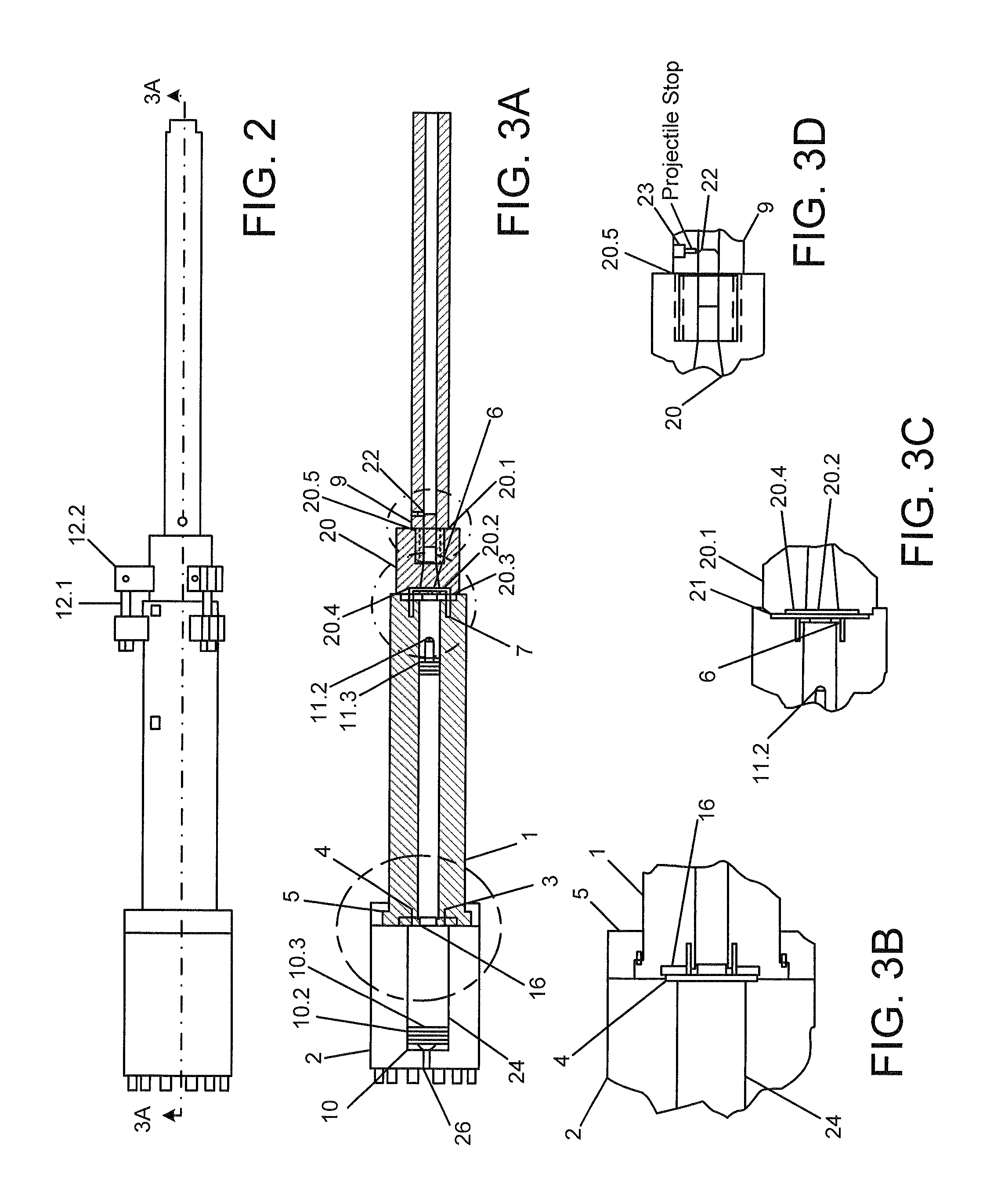
[0021]Referring to FIGS. 1-3D, the light gas gun of the present disclosure utilizes hydraulic pressure from a first amount of hydraulic oil from a hydraulic compression s...


PUM


Abstract

A stage light gas gun system and method capable of having a variable power output to match a specific use or application. The light gas gun uses a high pressure hydraulic oil system to provide a propulsive force behind two-stage piston system that is used to compress a light gas. The light gas gun may include a punch formed on the second piston for piercing a rupture disk at a pre-determined point in order to provide predictable performance.

Description

FIELD OF THE INVENTION[0001]The present disclosure relates to a device for accelerating a projectile and, more particularly, to a light gas gun.BACKGROUND OF THE INVENTION[0002]A light gas gun is a projectile launcher employing a gas having a low atomic number, usually hydrogen or helium. One limiting factor on the speed of a projectile coming from a gun is the speed of sound in the working fluid. This is because the pressure waves created by the propulsive force are essentially unable to propagate speeds higher than the speed of sound within a given medium. Thus, light gases are particularly advantageous for accelerating a projectile at very high velocities because the speed of sound in a gas is a function of the inverse square root of the molecular weight. The speed of sound also increases with the temperature of the fluid so that heat formed by the compression of the light gas also serves to increase the maximum possible speed.[0003]In a typical application, the light gas is pres...

Claims


Application Information

Patent Timeline
IPC IPC(8): F41A1/04
CPCF41A1/04
Inventor FUHRMAN, MICHAEL L.
Owner FUHRMAN MICHAEL L
Why Eureka
Try Eureka