Ankle derotation and subtalar stabilization orthosis

a subtalar stabilization and derotation technology, applied in the field ofankle derotation and subtalar stabilization orthosis, can solve the problems of abnormal rotary mobility within the tcj, transfer of torque to the leg, and extremely complex interrelationships of the ankle, and achieve the effect of restricting the inversion and translatory movement of the foo

Active Publication Date: 2012-06-19
WILKERSON GARY BLAINE
View PDF3 Cites 7 Cited by
  • Summary
  • Abstract
  • Description
  • Claims
  • Application Information

AI Technical Summary

Benefits of technology

[0017]An ankle taping procedure that incorporates tape strips applied in such a manner that their orientation is perpendicular to the orientation of the STJ axis has been shown to be highly effective in restricting inversion and translatory movement of the foot in relation to the leg (FIG. 9). Because the tape strips are anchored to the undersurface of the forefoot, span the joints of the forefoot and midfoot on the lateral aspect, and wrap around the leg in a posterior to medial direction, they have the effect of restraining subtalar inversion and anterolateral rotary displacement of the talus when the leg is externally rotated. Adustable-tension brace straps that originate on the lateral aspect of the ankle, wrap around the posterior and medial aspects of the leg, and anchor to a leg component have been previously disclosed (Bowman, U.S. Pat. No. 6,689,081; Broadhurst, U.S. Pat. No. 4,982,733; Hubbard, U.S. Pat. No. 5,944,678; Sutherland, U.S. Pat. No. 4,753,229), but none of them have originated from the lateral forefoot area. The present invention is an ankle derotation and subtalar stabilization system that incorporates a pivoting adjustable-tension oblique tether strap that is anchored to the forefoot and a contiguous pivoting adjustable-tension derotation strap that passes behind the leg.

Problems solved by technology

Although the ankle is widely viewed as a single joint between the leg and foot, ankle motion actually involves extremely complex interrelationships between the articular surfaces and ligaments of the talocrural joint, subtalar joint, transverse tarsal joint, tarsometatarsal joints, and metatarsophalangeal joints.
During weightbearing, frictional force between the ground and the foot results in the transfer of torque to the leg.
Tearing and / or chronic elongation of the ATFL results in abnormal rotary mobility within the TCJ (anterolateral rotary instability: anterior translation of the anterolateral portion of the talus from the tibio-fibular socket as the leg rotates externally; FIG. 8).

Method used


Image

  • Ankle derotation and subtalar stabilization orthosis
  • Ankle derotation and subtalar stabilization orthosis
  • Ankle derotation and subtalar stabilization orthosis

Examples


Embodiment Construction

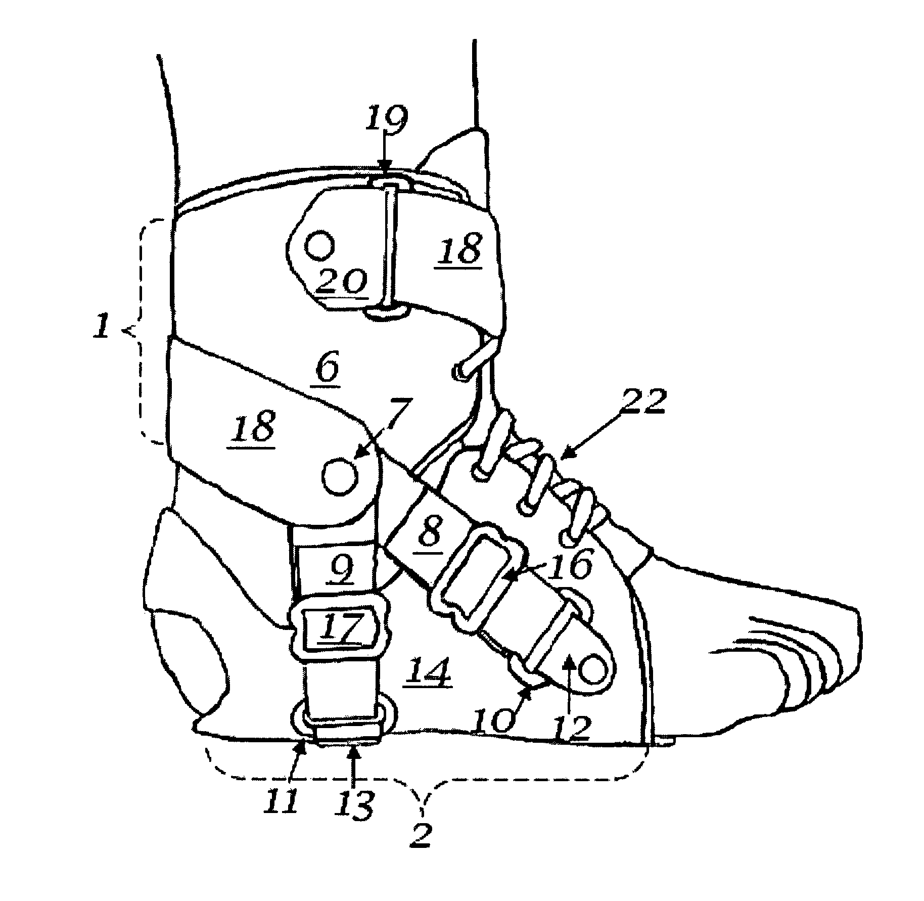
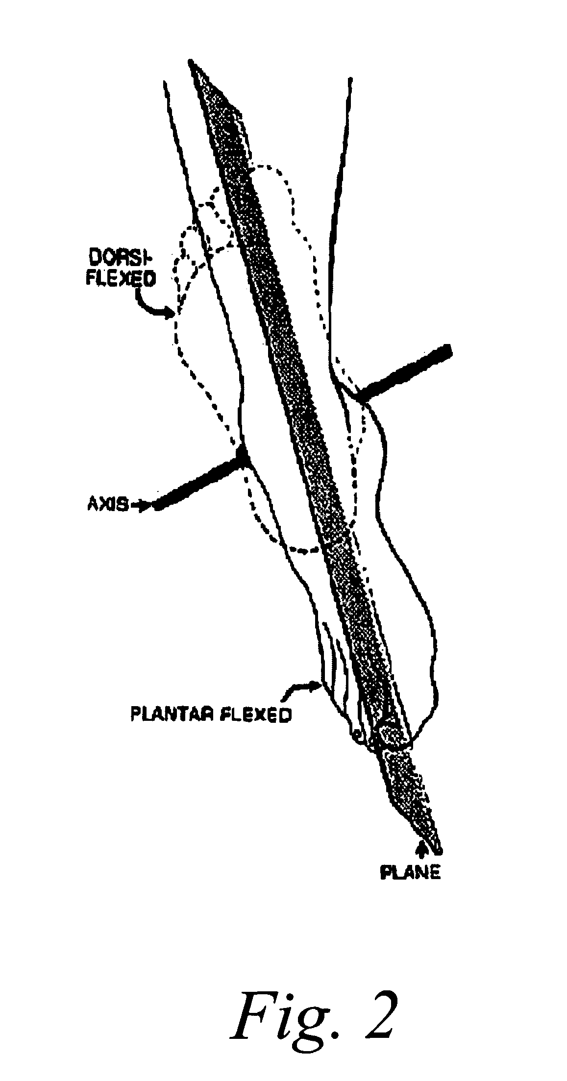
[0036]None of the prior art has disclosed an adjustable-tension tether strap that is anchored to the forefoot portion of a foot cuff / orthotic component, that pivots in a manner to permit normal upward and downward movement of the foot, and that is contiguous with a adjustable-tension derotation strap that wraps behind the leg and anchors to a leg cuff component. Because the major portion of forefoot motion results from rotation around the functional axis of the STJ, optimal resistance to excessive forefoot motion can be accomplished through a design that generates tensile resistance in a plane that is perpendicular to that of the STJ axis. Such a system requires moveable elements for the following reasons: 1) plantar flexion and dorsiflexion would be greatly limited by a non-elastic or non-articulated device that connects the leg and the forefoot, and 2) the orientation of the subtalar axis changes when the foot is dorsiflexed and plantar flexed.

[0037]The present invention is an ank...


PUM


Abstract

The invention is an ankle derotation and subtalar stabilization system that incorporates a pivoting adjustable-tension oblique tether strap that is anchored to both a forefoot component and leg component, and that is contiguous with pivoting adjustable-tension derotation strap that passes behind the leg and that is secured to a leg component. The system restrains oppositely directed rotation between the foot and the leg, and can actually after the normal biochemical relationship in a manner that produces foot rotation in a direction opposite to that which is normally coupled with leg rotation, without restriction of upward and downward foot movement. The primary application for the system is restraint of excessive subtalar joint inversion, leg external rotation, and anterolateral rotary displacement of the talus, but it can also be configured to restrain subtalar eversion and leg internal rotation through its incorporation into the structure of an ankle orthosis or shoe.

Description

CROSS REFERENCE TO RELATED APPLICATIONS[0001]This application claims benefit of Provisional application Ser. No. 60 / 846 / 738 filed Sep. 25, 2006.REFERENCES CITED[0002]U.S. PATENT DOCUMENTS4,237,874December 1980Nelson128 / 80 H4,441,265April 1984Burns et al. 36 / 1174,646,726March 1987Westin et al.128 / 80 H4,753,229January 1988Sutherland128 / 80 H4,982,733January 1991Broadhurst et al. 128 / 8045,031,607July 1991Peters128 / 60 H5,067,486November 1991Hely128 / 80 H5,209,722May 1993Miklaus et al.602 / 27Des 338,066August 1993BaronD24 / 1925,472,411December 1995Montag, et al.602 / 235,810,754September 1998Kenosh602 / 275,899,872May 1999Gilmour602 / 655,944,678August 1999Hubbard602 / 275,971,946October 1999Quinn et al.602 / 276,053,884April 2000Peters602 / 276,056,713May 2000Hayashi602 / 276,228,043 B1May 2001Townsend et al.602 / 276,602,215 B1August 2003Richie, Jr.602 / 276,793,640 B1September 2004Avon602 / 236,689,081 B2February 2004Bowman602 / 27OTHER PUBLICATIONS[0003]Wilkerson G B, Kovaleski J E, Meyer M A. Stawitz C E. Ef...

Claims


Application Information

Patent Timeline
Patent Type & Authority Patents(United States)
IPC IPC(8): A61F5/00
CPCA61F5/0127A61L15/07
Inventor WILKERSON, GARY BLAINE
Owner WILKERSON GARY BLAINE
Why Eureka
Try Eureka