Air pollution control apparatus and air pollution control method

a technology of air pollution control and air pollution, which is applied in the direction of chemical/physical processes, inorganic chemistry, hydrogen sulfides, etc., can solve the problem that conventional techniques cannot draw the total amount of flue gas from a boiler, a gas turbine,

Active Publication Date: 2012-06-19
MITSUBISHI HEAVY IND ENG LTD
View PDF23 Cites 83 Cited by
  • Summary
  • Abstract
  • Description
  • Claims
  • Application Information

AI Technical Summary

Benefits of technology

[0022]According to still another aspect of the present invention, an air pollution control method includes mixing flue gas discharged from an industrial facility and atmosphere flowing in from outside of a stack to prevent the atmosphere from flowing further inside of the stack.

Problems solved by technology

However, no conventional techniques draw the total amount of flue gas from a boiler, a gas turbine, or the like to be discharged from a stack to the atmosphere into a CO2 recovering apparatus.

Method used


Image

  • Air pollution control apparatus and air pollution control method
  • Air pollution control apparatus and air pollution control method
  • Air pollution control apparatus and air pollution control method

Examples


first embodiment

[0035]An air pollution control apparatus according to an embodiment of the present invention is explained with reference to FIG. 1.

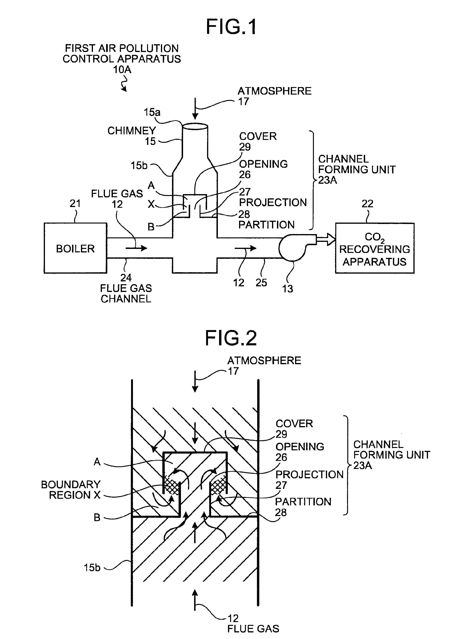
[0036]FIG. 1 is a schematic of a configuration of this air pollution control apparatus according to a first embodiment of the present invention. FIG. 2 is a partially enlarged schematic of a configuration of the inside of a stack. In FIGS. 1 and 2, components that are the same as their counterparts shown in FIG. 9 are provided with the same symbols, and are not explained repeatedly.

[0037]As shown in FIG. 1, a first air pollution control apparatus 10A according to the first embodiment of the present invention includes: a stack 15 that discharges, to the outside, flue gas 12 discharged from a boiler 21, a gas turbine, or the like provided in an industrial facility; a blower 13 that is provided downstream of the stack 15, and draws in the flue gas 12; and a CO2 recovering apparatus 22 that recovers CO2 in the flue gas 12 drawn in by the blower 13. The first...

second embodiment

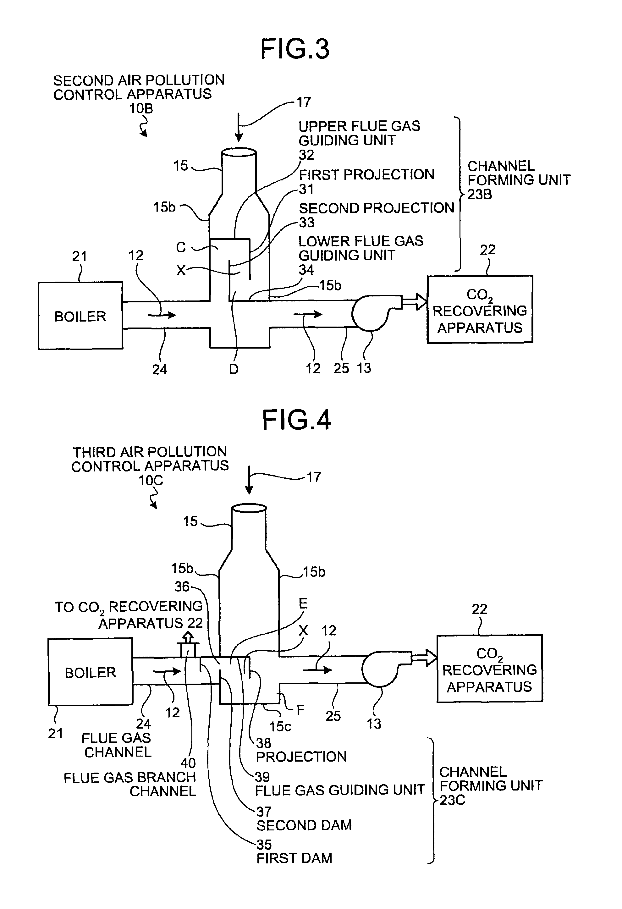
[0044]FIG. 3 is a schematic of a configuration of an air pollution control apparatus according to a second embodiment of the present invention. The air pollution control apparatus according to the present embodiment is explained with reference to FIG. 3. Components that are the same as the counterparts in the air pollution control apparatus according to the first embodiment are provided with the same symbols, and are not explained repeatedly.

[0045]In this second air pollution control apparatus 10B according to the present embodiment, a channel forming unit 23B used as a controlling unit includes: an upper flue gas guiding unit 32 extending from the wall surface 15b of the stack 15 on the side in which the flue gas 12 flows when viewed from the cross-sectional direction in the longitudinal direction of the stack 15 and including, at its leading end, a first projection 31 that projects downward; and a lower flue gas guiding unit 34 extending from the inner wall 15b of the stack 15 on ...

third embodiment

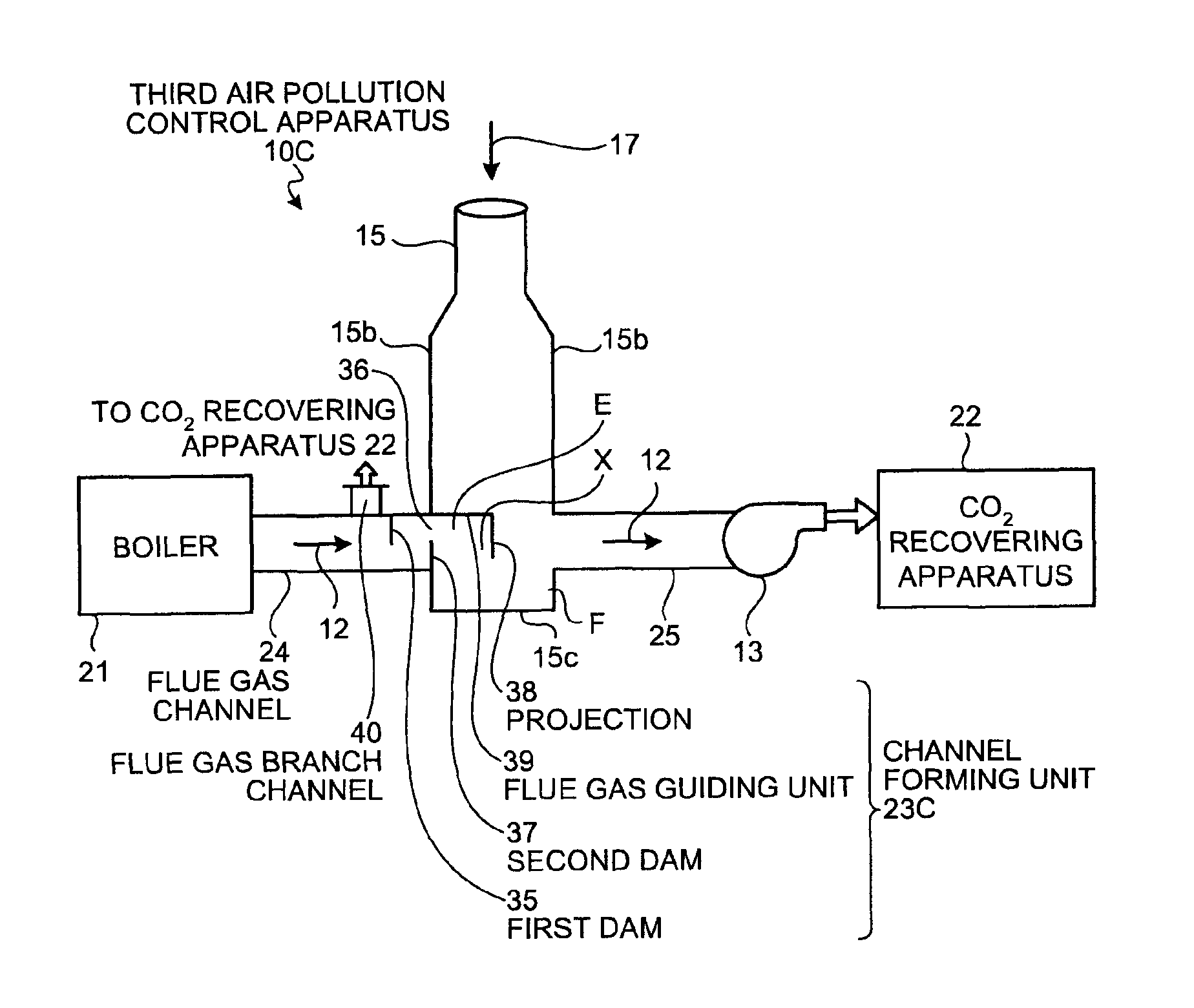
[0050]FIG. 4 is a schematic of a configuration of an air pollution control apparatus according to a third embodiment of the present invention. The air pollution control apparatus according to the present embodiment is explained with reference to FIG. 4. Components that are the same as the counterparts in the air pollution control apparatus according to the first embodiment are provided with the same symbols, and are not explained repeatedly.

[0051]In this third air pollution control apparatus 10C according to the present embodiment, a channel forming unit 23C used as a controlling unit includes a first dam 35 provided at the upper portion of the flue gas channel 24 through which the flue gas 12 is fed from the boiler 21 to the stack 15 when viewed from the cross-sectional direction in the longitudinal direction of the stack 15, a second dam 37 provided at the lower portion of an inlet 36 of the stack 15 through which the flue gas 12 is fed to the stack 15, and a flue gas guiding unit...


PUM

PropertyMeasurementUnit
densityaaaaaaaaaa
temperatureaaaaaaaaaa

Abstract

An air pollution control apparatus according to an embodiment of the present invention includes: a stack that discharges flue gas discharged from a boiler outside; a blower that is provided downstream of the stack and draws in the flue gas; and a CO2 recovering apparatus that recovers CO2 in the flue gas drawn in by the blower. The stack includes a controlling unit that suppresses release of the flue gas outside from the stack and suppresses inflow of atmosphere to the stack, and the controlling unit is a channel forming unit that forms a serpentine channel through which the flue gas and the atmosphere in the stack flow.

Description

BACKGROUND OF THE INVENTION[0001]1. Field of the Invention[0002]The present invention relates to an air pollution control apparatus and an air pollution control method that suppress discharge, to the atmosphere, of flue gas discharged from a boiler and the like.[0003]2. Description of the Related Art[0004]Recently, the greenhouse effect of CO2 has been pointed out as a cause of global warming, and a countermeasure against it has become an international urgent task for protecting the global environment. The source of CO2 ranges over every kind of human activities involving burning of fossil fuels, and the trend is toward further demand for the suppression of CO2 discharge. Along with the trend, a method of bringing burnt flue gas from a boiler into contact with amine CO2 absorbing solution and reducing and recovering CO2 in the burnt flue gas, and a method of preserving recovered CO2 without releasing it to the atmosphere have been strenuously studied for use at a power generating fa...

Claims


Application Information

Patent Timeline
Patent Type & Authority Patents(United States)
IPC IPC(8): B01D45/00C01B32/50
CPCB01D53/346B01D53/62F23J15/006F23L11/00F23L13/06F23L17/005B01D2257/504Y02C10/04F23J2217/20F23J2215/50Y10T137/4643Y10T137/86212Y02C20/40Y02E20/32
Inventor IIJIMA, MASAKI
Owner MITSUBISHI HEAVY IND ENG LTD
Why Eureka
Try Eureka