Head for application of carbon-fibre strips and application method

a carbon fiber and strip technology, applied in the field of parts manufacturing, can solve the problems of increasing the size of parts, increasing the complexity, and the surface of parts, and achieve the effect of correct application tension and better exploitation

Inactive Publication Date: 2012-06-19
THE NATH LAW GROUP
View PDF14 Cites 1 Cited by
  • Summary
  • Abstract
  • Description
  • Claims
  • Application Information

AI Technical Summary

Benefits of technology

[0014]A head is thus obtained by means of which strips of different widths, the same or not, can be applied for the formation of a stripping with an application width equivalent to that of a very wide band, which allows establishing, by means of controlling the transmission of the rotary actuation to the reels of the carbon-fibre strips, the continuous or uninterrupted application of each of the strips, according to the requirements of the surface to be formed, as well as individually varying the speed of the feed of the different strips, for adapting the application on the curves of the surface to be formed, which allows offsetting the greater range of travel for the application in the outer part of the curve than in the inner part, maintaining the tension in the strips used along the entire width of the application, without them being deformed.
[0017]In relation to the feed of each carbon-fibre strip from the corresponding reels, an independent sensor is arranged whereby controlling the actuation of the rotary transmission to the reels is to adjust the application speed of each of the strips as needed, maintaining a correct application tension in said strips. Said sensors are furthermore provided with an oscillating movement arrangement, which allows offsetting the variation of inertia of the reels according to the amount of the strip thereof consumed.
[0018]The replacement of the strip-holding reels can be done individually, when the strip contained therein runs out, in each case changing the reel that runs out, or replacing the entire group of reels when one of them runs out, which reduces the number of necessary replacements and stops but entails the waste of the material remaining on the unfinished reels.
[0019]An alternative for achieving a better exploitation of the strips for application with a minimum number of replacements of the reels holding said strips consists of applying a software program for managing the feed of the strips in combination with a programme of successive uses of the applicator head for the formation of different parts, such that the software calculates the ranges of travel that must be performed in the different uses for applying the stripping in order to perform these uses such that the greater consumption of strips in application uses is offset with the greater consumption of the other strips in other uses, whereby all the reels holding the strips for application run out at the same time and can be replaced at the same time, without wasting the material thereof.
[0021]The overall working time in applying the carbon-fibre strips is thus considerably reduced, since the strips are applied and the remainder thereof is cut with the same head, furthermore being a much simpler and cheaper assembly of the necessary means, since the operative positioning of the cutting unit is done by means of rotating the head on one of its own assembly shafts.

Problems solved by technology

However, the increase in the size of the parts involves at the same time an increase in the complexity thereof, machinery capable of fulfilling the qualities of the application in the complexity conditions of the large parts being required.
Thus, for example, the complexity of the surface of the parts includes the providing curved areas, which in the formations by means of laying strips of carbon fibre, as is done in the construction of aeronautical parts, involves a problem since the radii of curvature which can be made depend on the width of the carbon-fibre bands which are used in the application, such that the greater the width of the band which is applied, the less the radius of the curvatures which can be made in the application must be closed, i.e., a larger radius is necessary to avoid wrinkles in the band used.
The width of the band for application proportionally affects the productivity of the processes for forming the parts by means of said strip laying with carbon fibre, such that the smaller the width of the stripping for application, the greater the number of passes that have to be performed and, therefore, the greater the amount of time necessary and the lower the productivity.

Method used


Image

  • Head for application of carbon-fibre strips and application method
  • Head for application of carbon-fibre strips and application method
  • Head for application of carbon-fibre strips and application method

Examples


Embodiment Construction

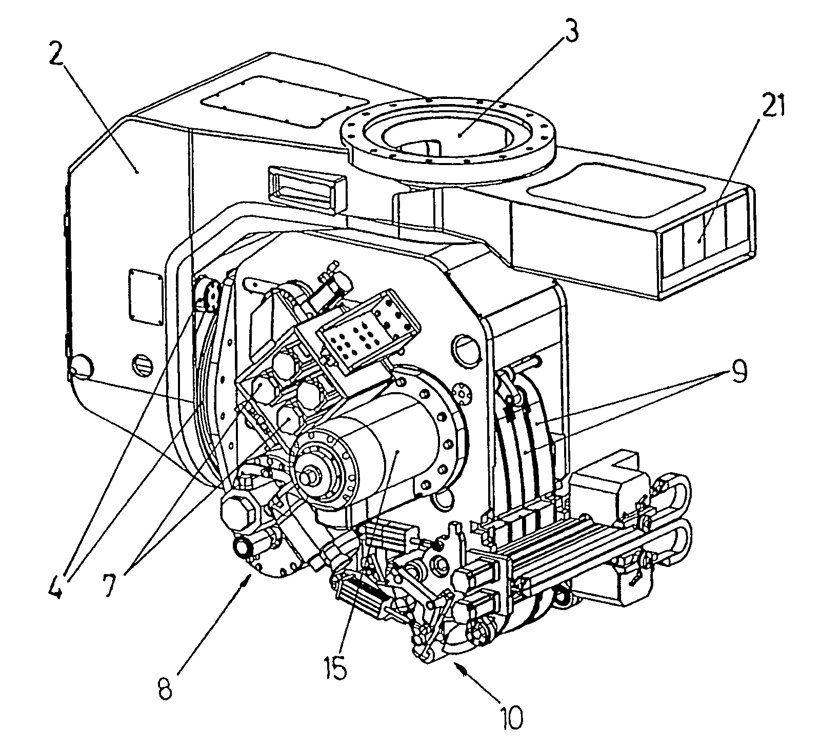
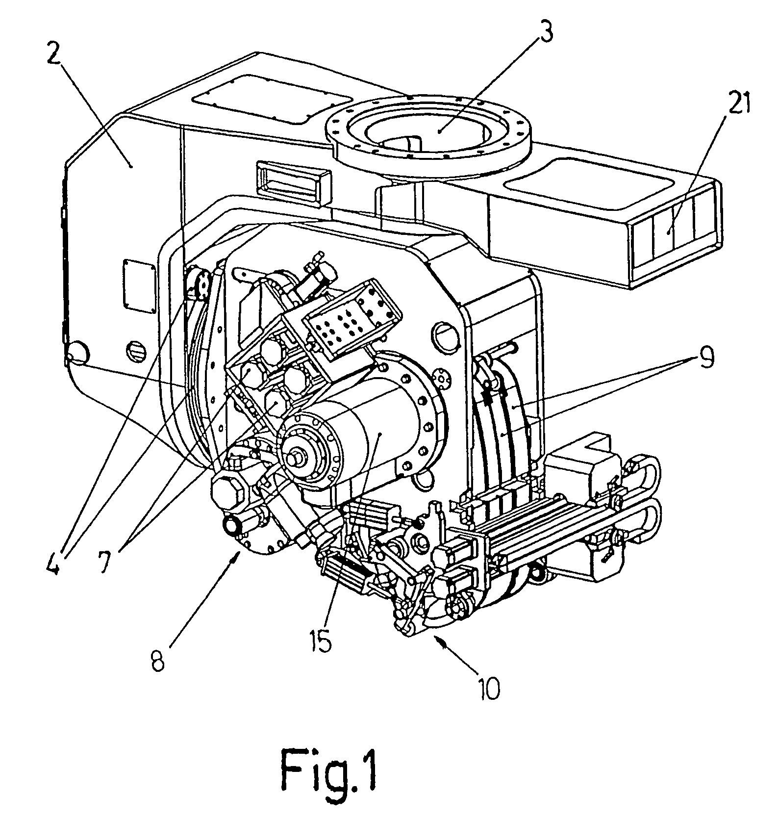
[0039]The object of the invention relates to a head for the application of carbon-fibre strips for forming parts for the aeronautical industry or the like, with improvements in the head used for said function and in the application method.

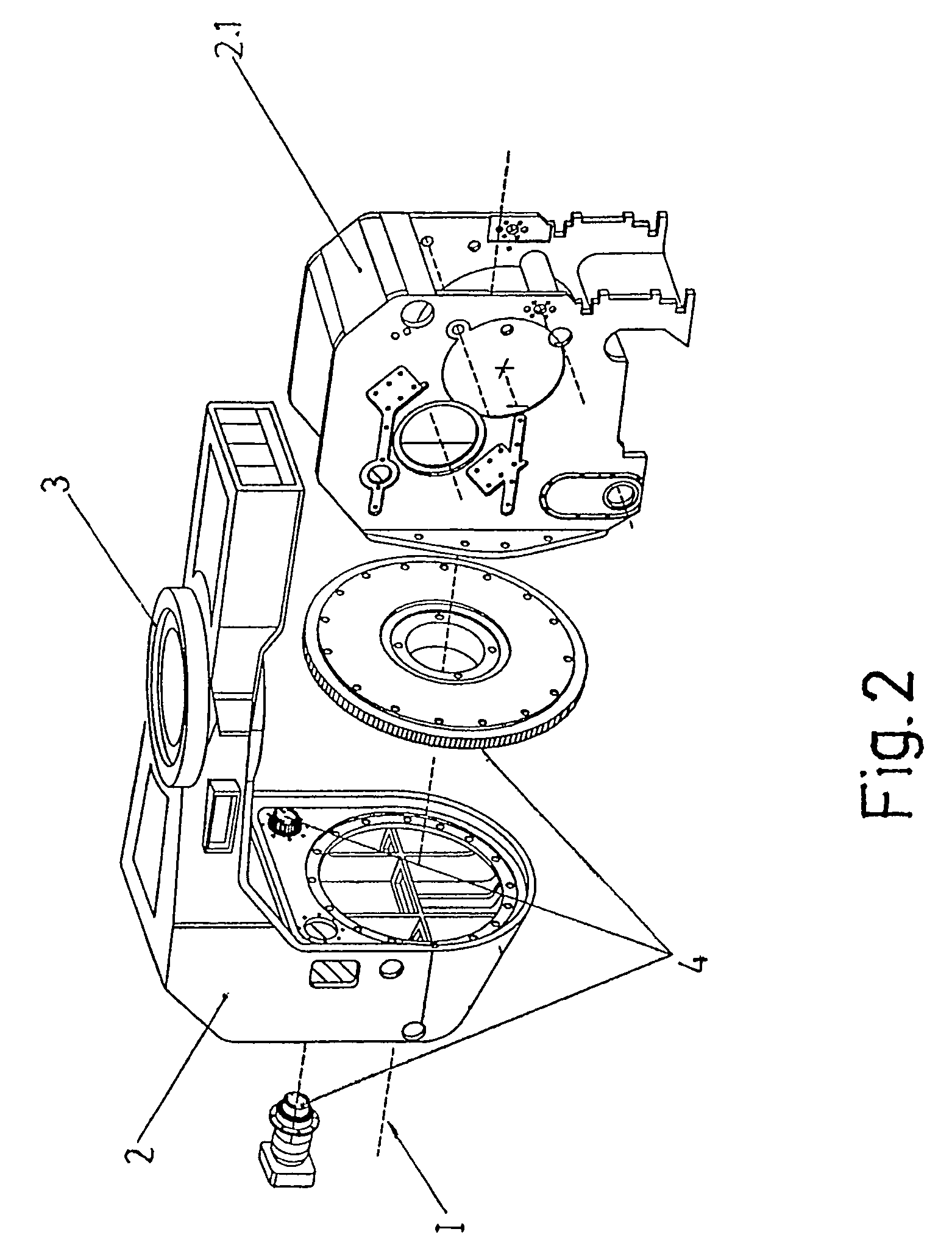
[0040]The head is conventionally arranged on a rotary movement support (2) with respect to an assembly coupling (3) of vertical axis III, whereas the block (2.1) or actual head is incorporated in “pinion-crown” rotary assembly (4) of the horizontal axis I on the mentioned support (2), see FIGS. 1, 2 and 3.

[0041]According to the invention, at least two carbon strip feed reels (1) for feeding the carbon strips to be applied are arranged in the head.

[0042]According to the non-limiting practical embodiment which is depicted in the attached drawings, the head has, as is seen in FIG. 10, four reels (1), on each of which a carbon-fibre strip with a width measurement of 75 mm is wound. Thus, if the head applies the four carbon-fibre strips at the same time...


PUM

PropertyMeasurementUnit
widthaaaaaaaaaa
widthaaaaaaaaaa
widthaaaaaaaaaa

Abstract

The invention relates to a head for application of carbon-fibre strips that has at least two spools (1) conveying respective carbon-fibre strips for the selective feed of said strips and in order thus with said strips to make up the width of the stripping for application. These spools (1) are arranged on a master roller (5) formed by independent sections that are actuated individually by respective rotary transmissions.

Description

FIELD OF THE ART[0001]The present invention relates to the manufacture of parts, by means of applying strips of carbon fibre, especially for the aeronautical industry, proposing a system with particular features in relation to an applicator head with multiple strips and the application method for applying said strips on the surface to be formed.STATE OF THE ART[0002]In the construction of aeronautical structures the joints between the component parts are the most critical resistance parts, whereby the largest possible parts tend to be used for the purpose of reducing the number of joints.[0003]However, the increase in the size of the parts involves at the same time an increase in the complexity thereof, machinery capable of fulfilling the qualities of the application in the complexity conditions of the large parts being required.[0004]Thus, for example, the complexity of the surface of the parts includes the providing curved areas, which in the formations by means of laying strips o...

Claims


Application Information

Patent Timeline
Patent Type & Authority Patents(United States)
IPC IPC(8): B65H81/00
CPCB29C70/38B29C70/388B29C70/545Y10T156/17Y10T156/1348B29C53/80
Inventor TORRES MARTINEZ, MANUEL
Owner THE NATH LAW GROUP
Why Eureka
Try Eureka