Power safety system

a power safety and system technology, applied in the direction of safety/protection circuits, emergency protective arrangements for limiting excess voltage/current, transportation and packaging, etc., can solve the problems of reverse current, inconvenience of use, and single power supply powered by a single alternating-current (ac) or direct-current (dc) power supply that does not have much portability, so as to enhance efficiency and reduce the size and cost of the circui

Inactive Publication Date: 2012-06-19
RICHTEK TECH
View PDF3 Cites 12 Cited by
  • Summary
  • Abstract
  • Description
  • Claims
  • Application Information

AI Technical Summary

Benefits of technology

[0008]It is another object of the present invention to provide a highly efficient power safety system.
[0009]It is a further object of the present invention to provide a smaller and lower cost power safety system.
[0012]By switching the body of the first MOS transistor to the source or the drain of the first MOS transistor, the bias direction of a parasitic diode of the first MOS transistor is controlled so as to prevent a reverse current which might otherwise flow from the power output to the power input. In a power safety system according to the present invention, no additional diodes or MOS transistors are required for separating the circuit of the power safety system from a power supply or a battery. Consequently, the efficiency is enhanced while the size and cost of the circuit are reduced. Besides, the switch and the body controller can be implemented by very small circuits and integrated into a controller chip.

Problems solved by technology

Devices powered by a single alternating-current (AC) or direct-current (DC) power supply do not have much portability.
While battery-driven devices are portable, the limited energy capacity of batteries leads to inconvenience of use.
However, when applied to a device that is powered by both a power supply and a battery, this type of battery charger may result in reverse current.
Even if the MOS transistors M1 and M3 both are turned off, the reverse current can flow to the AC power supply ACIN through the parasitic diodes D1 and D3, thus reducing the service life of the battery 10.
However, the diode D4 will cause the voltage V4 to be lower than the voltage at the AC power supply ACIN by a forward bias of the diode D4 and thereby reduce the efficiency of charging the battery 10.
This approach requires relatively complex control.
Also, the addition of the MOS transistor M2 lowers the efficiency.
Those voltage drops result in lower efficiency.
In addition, the use of the diode D4 or the MOS transistor M2 increases the size and cost of the circuit.
The power components, which are large and expensive, significantly increase the size and cost of the circuit.
Nowadays, all these power components are external separated components that cannot be integrated into a controller chip, making it impossible to reduce the size and cost of the whole circuit.
The problems mentioned above also exist in other similar systems such as those using an AC / DC converter or a USB-based DC power supply in place of the aforesaid AC power supply ACIN.

Method used


Image

  • Power safety system
  • Power safety system
  • Power safety system

Examples


Embodiment Construction

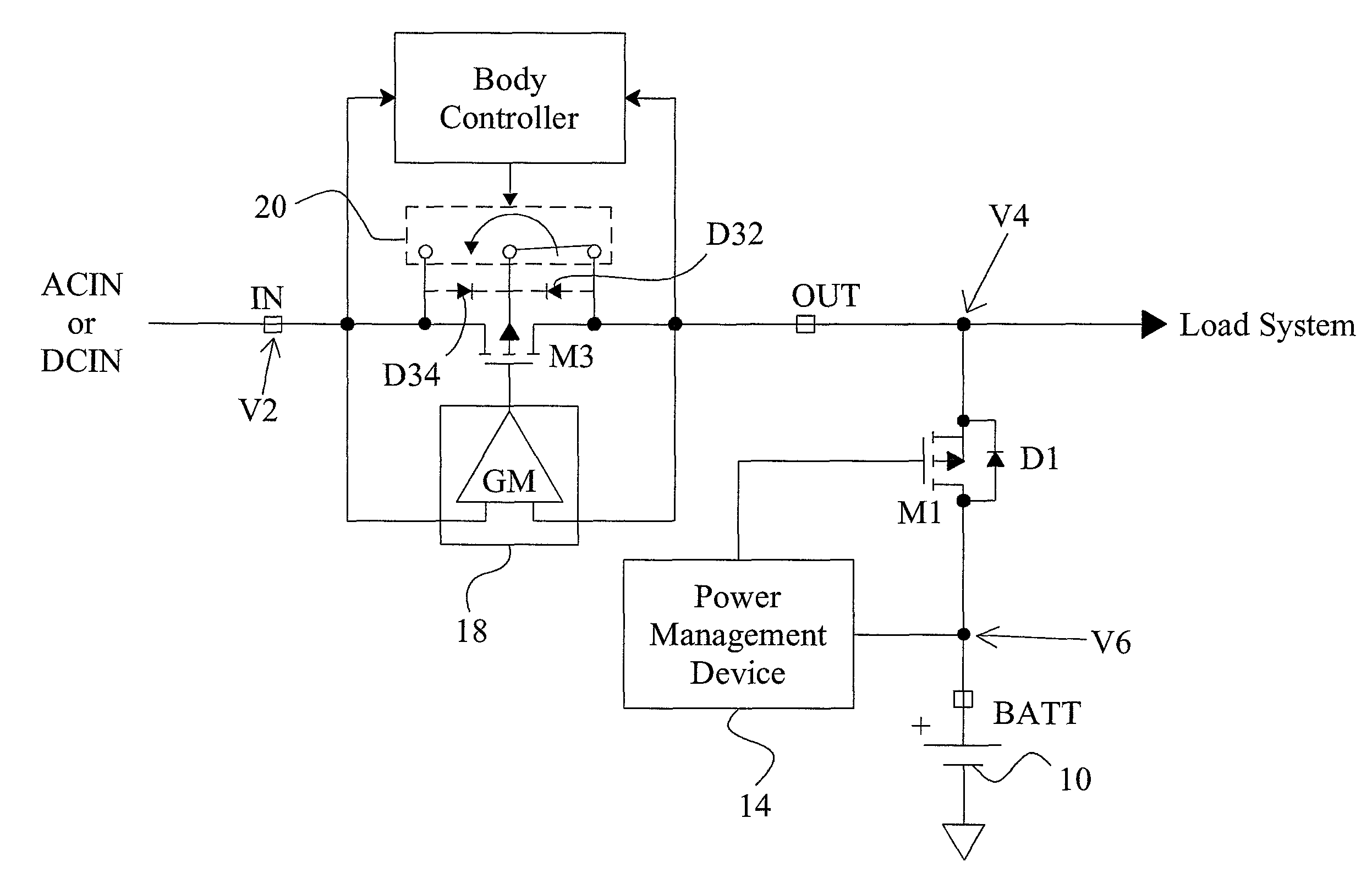
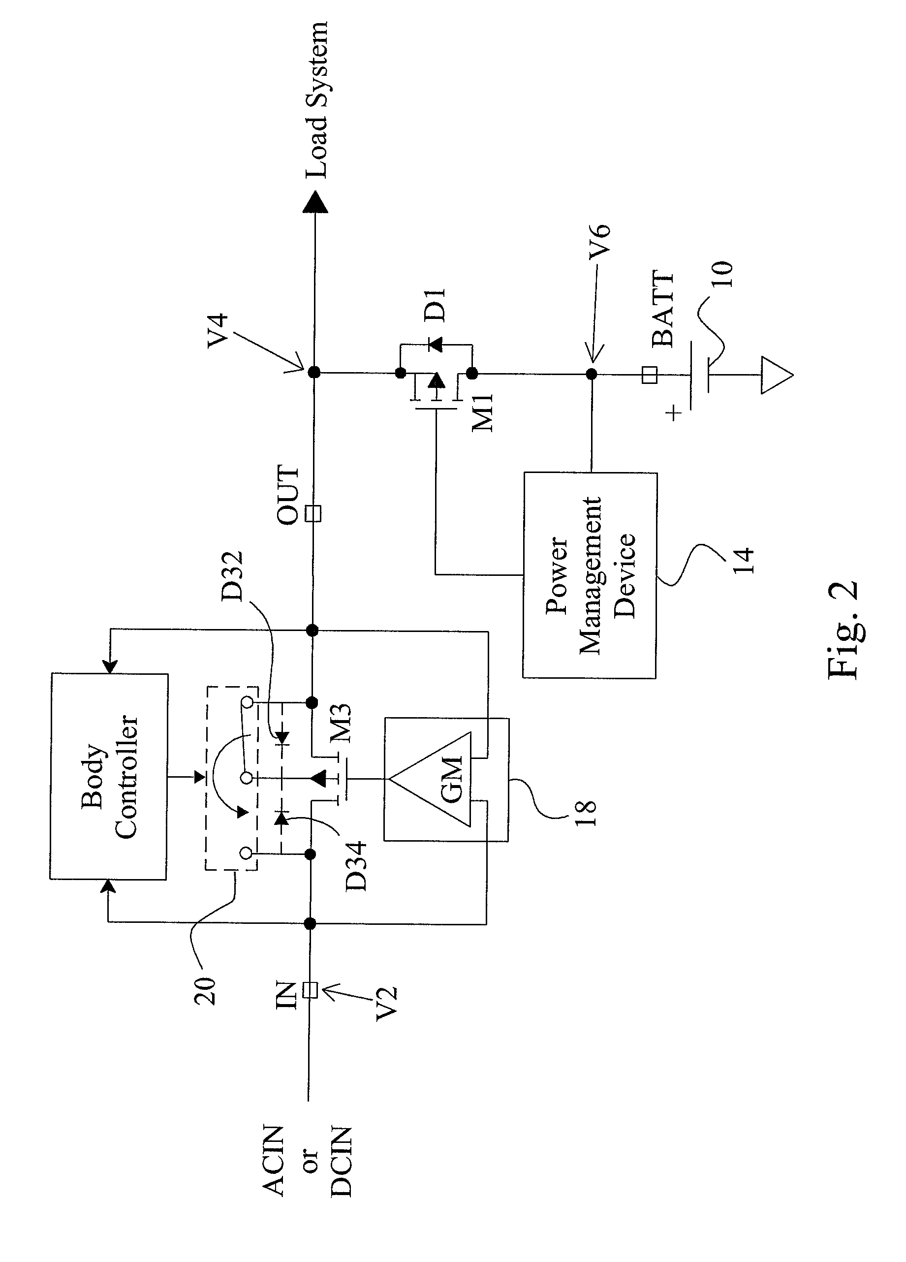
[0016]When a MOS transistor has its body connected to its source or drain, a parasitic diode is formed between the source and the drain due to the PN junction in the semiconductor structure. The bias direction of this parasitic diode can be controlled by selectively connecting the body of the MOS transistor to the source or the drain of the MOS transistor.

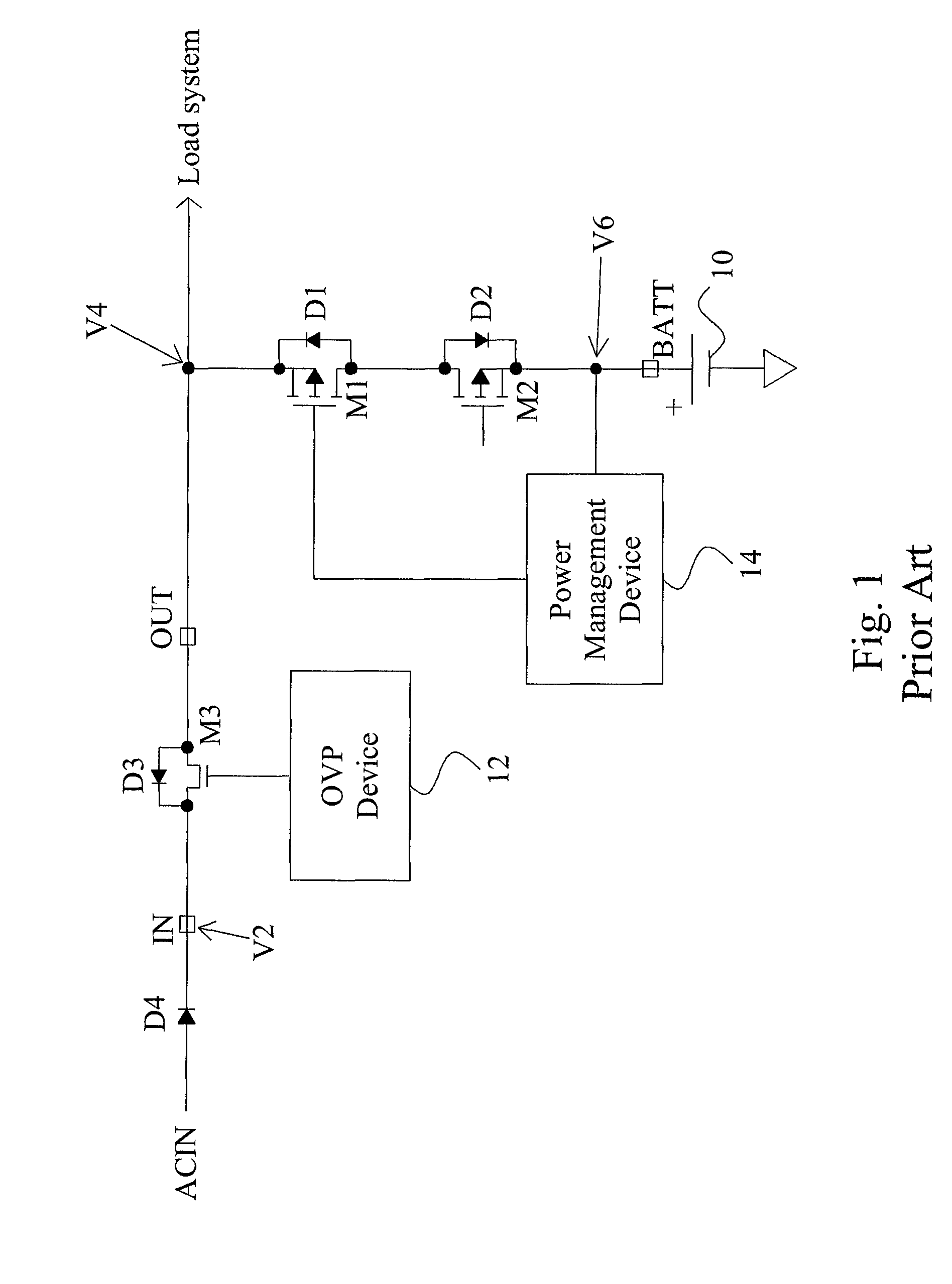
[0017]FIG. 2 is a circuit diagram of an embodiment according to the present invention, in which a power safety system has a similar circuit design to that depicted in FIG. 1. This power safety system includes a power input IN to be connected with an AC power supply ACIN or a DC power supply DCIN, a power output OUT to be connected to a load system, a MOS transistor M3 connected between the power input IN and the power output OUT, an amplifier 18 connected to the power input IN, the power output OUT, and a gate of the MOS transistor M3, a charging output BATT to be connected to a battery 10, a MOS transistor M1 connected between the...


PUM


Abstract

A power safety system includes a first MOS, a second MOS, a switch and a body controller. The first MOS is connected between a power input and a power output. The second MOSFET is connected between the power output and a charging output. The switch has an end connected to the body of the first MOS, and the opposite end switched between the source and the drain of the first MOS. A body controller controls the switch according to the voltage at the power input and the voltage at the power output, to connect the body of the first MOS to the source or the drain of the first MOS. By switching the switch, the first MOS will have a parasitic diode effective to prevent a reverse current from the power output to the power input.

Description

FIELD OF THE INVENTION[0001]The present invention is related generally to a power safety system and, more particularly, to a circuit and method for preventing a reverse current in a power safety system.BACKGROUND OF THE INVENTION[0002]Devices powered by a single alternating-current (AC) or direct-current (DC) power supply do not have much portability. While battery-driven devices are portable, the limited energy capacity of batteries leads to inconvenience of use. A device that can be powered by both a power supply and a battery is configured in such a way that the power supply and the battery are connected in parallel to a load system and that at least a diode is connected in series between the battery and the load system. If the battery is rechargeable, a charger is additionally provided so as to charge the battery while an AC or DC power supply is being used. Thus, the battery has its service life extended, and the frequency of battery change is reduced. Recently, it is common pr...

Claims


Application Information

Patent Timeline
Patent Type & Authority Patents(United States)
IPC IPC(8): H02J1/10H02J3/38
CPCH02J7/0031H02J7/0029
Inventor LEE, LI-WEIKUNG, NIEN-HUICHU, KWAN-JENCHEN, CHUN-TSUNG
Owner RICHTEK TECH
Why Eureka
Try Eureka