Pulse detonation/deflagration apparatus and related methods for enhancing DDT wave production

a technology of ddt wave and actuator, which is applied in the direction of intermittent jet plants, vessel construction, marine propulsion, etc., can solve the problems of increasing the operating frequency or magnitude of pulsed output, occupying additional space, and adding external tubes and high-speed valves. to achieve the effect of increasing the magnitude of pressure wave output and increasing the operating frequency

Active Publication Date: 2012-06-26
LOCKHEED MARTIN CORP
View PDF16 Cites 23 Cited by
  • Summary
  • Abstract
  • Description
  • Claims
  • Application Information

AI Technical Summary

Benefits of technology

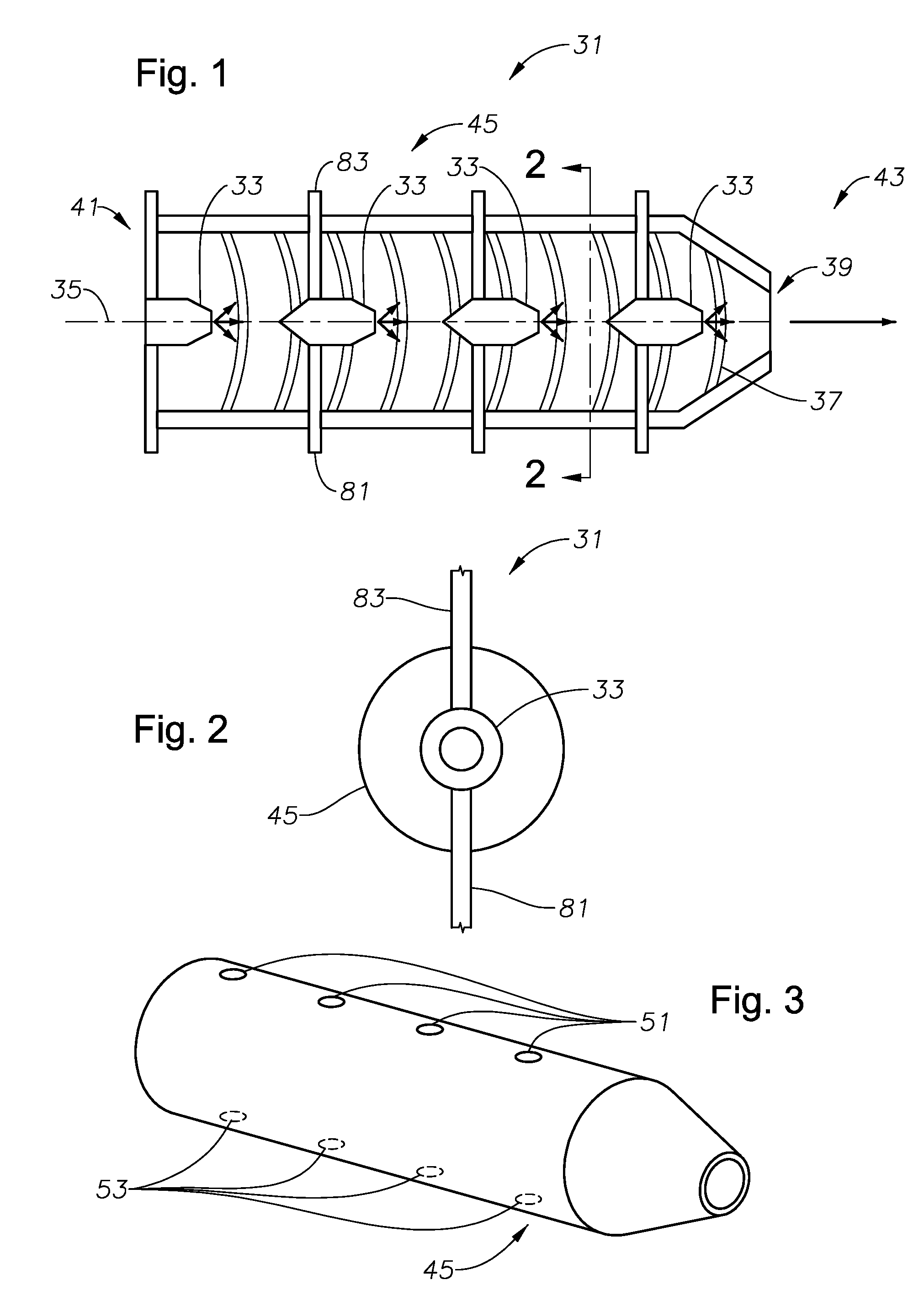
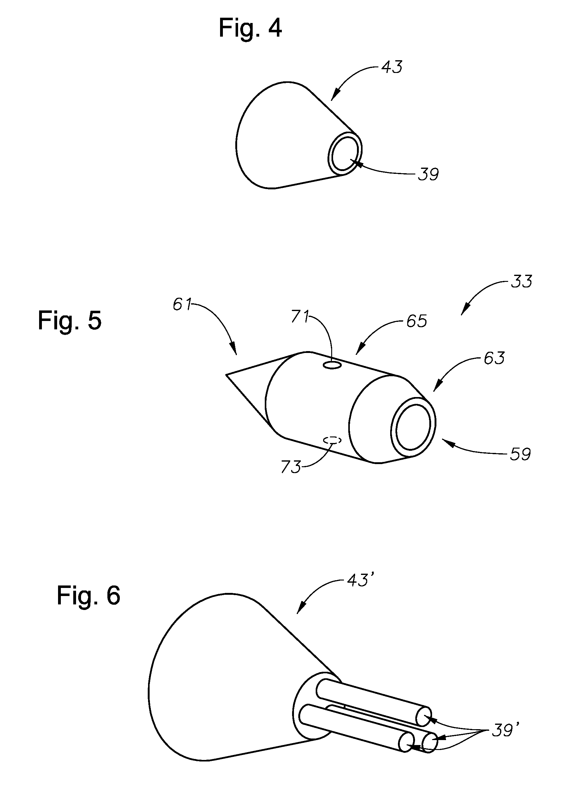
[0009]In view of the foregoing, embodiments of the present invention advantageously provide pulse deflagration / detonation apparatus and methods of enhancing deflagration to detonation wave production. Embodiments of the present invention also advantageously provide an apparatus including one or more high frequency in-line pulsed detonation / deflagration actuators or engines. Embodiments of the present invention advantageously overcome the difficulties of prior systems by providing a single containment pulse detonation / deflagration actuator / engine (PDA / E) tube with multiple smaller individual combustion PDA / E tubes separately longitudinally or radially positioned entirely within the containment PDA / E tube, whereby initial combustion takes place inside each of the smaller combustion PDA / E tubes, which is released into the larger containment PDA / E tube. Embodiments of the present invention also advantageously provide an apparatus including one or more multi-channel pulse detonation / deflagration actuators / engines, which can be readily implemented for nozzle area control & thrust vectoring.
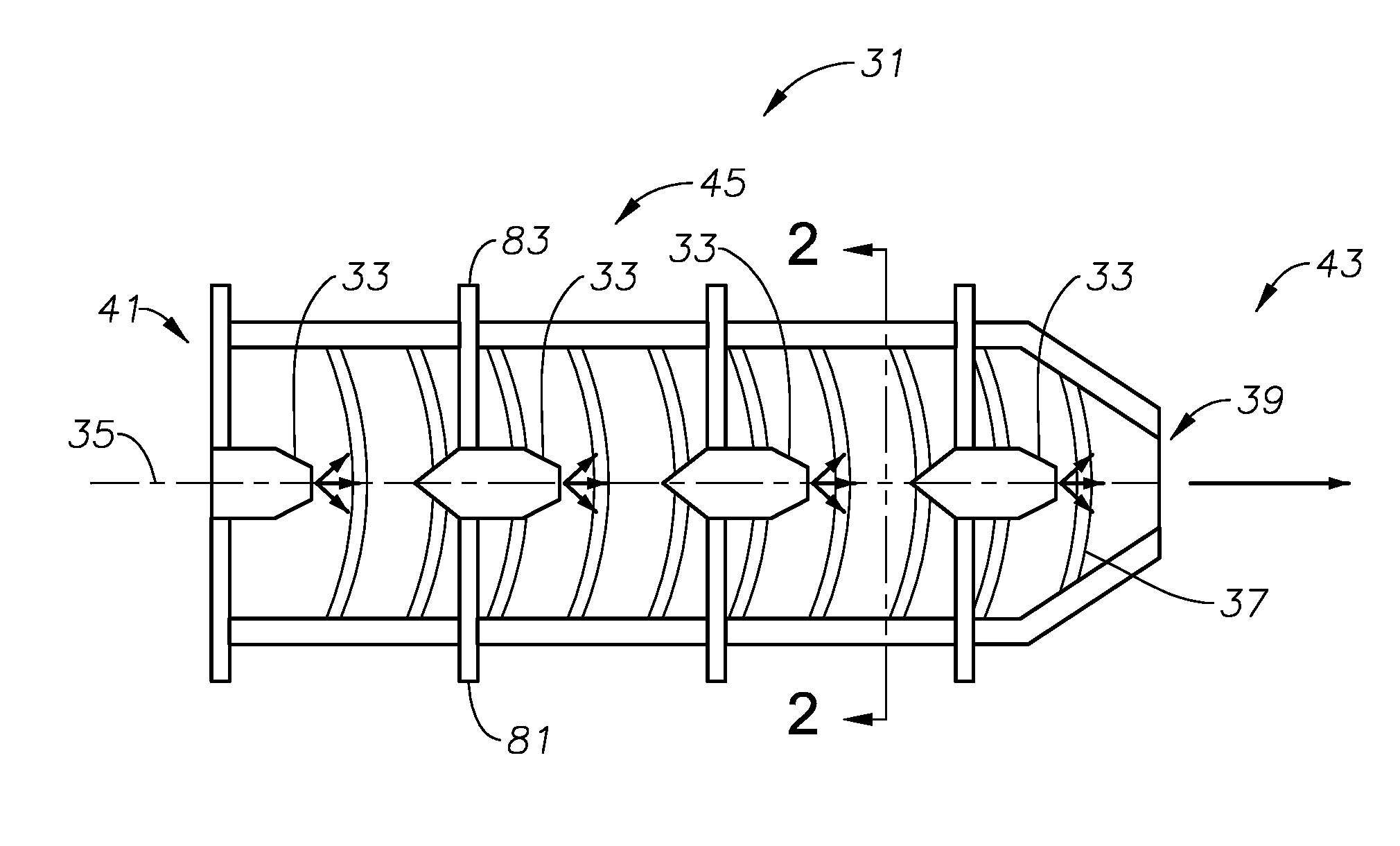
[0011]According to an embodiment of the apparatus, the internal pulse detonation chambers are positioned longitudinally along a common longitudinal axis so that deflagration to detonation waves generated by each separate one of the plurality of internal pulse detonation chambers, travel in-line with each other and exit out the aperture in the distal end portion of the main pulse detonation chamber, thus, increasing the overall operating frequency of the apparatus. According to another embodiment of the apparatus, the internal pulse detonation chambers are separately radially positioned within the main body of the main pulse detonation chamber so that deflagration to detonation waves exiting through the aperture in the distal end portion of the main pulse detonation are at a higher magnitude than individual deflagration to detonation waves generated by any separate one of the plurality of internal pulse detonation chambers.
[0014]The method can also include the step of positioning each of the plurality of separate internal pulse detonation chambers longitudinally along a common longitudinal axis so that deflagration to detonation waves generated by each separate one of the plurality of internal pulse detonation chambers travel in-line with each other and exit out the one or more common exhaust apertures. Correspondingly, according to such embodiment of the method, the step of oxidizing fuel within each of a plurality of internal pulse detonation chambers can include the step of firing each of the plurality of internal pulse detonation chambers in a sequential order to thereby increase operating frequency.
[0015]According to an alternative embodiment of the present invention, the method can include the step of positioning each of the plurality of separate internal pulse detonation chambers along a common radial plane within the main body of the main pulse detonation chamber so that deflagration to detonation waves exiting through the aperture in the distal end portion of the main pulse detonation are at a higher magnitude than individual deflagration to detonation waves generated by any separate one of the plurality of internal pulse detonation chambers. Correspondingly, according to such an embodiment of the method, the step of oxidizing fuel within each of the plurality of internal pulse detonation chambers can include the step of firing each of the plurality of internal pulse detonation chambers at substantially the same time to thereby increase pressure wave output magnitude.

Problems solved by technology

Methods to increase the operating frequency or magnitude of the pulsed output to try to obtain high aggregate operating frequencies and quasi-steady thrust have been generally limited to new valve techniques combined with multiple external tubes linked together and configured to perform slightly out of phase.
Such additional external tubes and high-speed valves, however, not only occupy additional space and add additional weight, but they can also add an additional level of complexity.
Fluids in motion will have undesirable flow areas and areas that need directional control.

Method used


Image

  • Pulse detonation/deflagration apparatus and related methods for enhancing DDT wave production
  • Pulse detonation/deflagration apparatus and related methods for enhancing DDT wave production
  • Pulse detonation/deflagration apparatus and related methods for enhancing DDT wave production

Examples


Embodiment Construction

[0027]The present invention will now be described more fully hereinafter with reference to the accompanying drawings, which illustrate embodiments of the invention. This invention may, however, be embodied in many different forms and should not be construed as limited to the illustrated embodiments set forth herein. Rather, these embodiments are provided so that this disclosure will be thorough and complete, and will fully convey the scope of the invention to those skilled in the art. Like numbers refer to like elements throughout.

[0028]FIGS. 1-10 illustrate a pulse detonation / deflagration apparatus 30, 30′, for producing highly pressurized detonation waves, which can be used to create thrust for propulsion, and / or vectoring thrust and jet engine nozzle area control. Referring to FIGS. 1 and 2, an embodiment of the present invention includes apparatus 30 having a main pulse detonation chamber, e.g., a single main / outer pulse detonation / deflagration actuator / engine (PDA / E) tube 31, c...


PUM


Abstract

Pulse detonation / deflagration apparatus for providing enhanced pressure wave operating frequency and / or magnitude, and methods of increasing the frequency or the magnitude of deflagration to detonation waves, are provided. A pulse detonation / deflagration apparatus can include a main / outer pulse detonation / deflagration actuator / engine (PDA / E) with multiple smaller internal combustion chambers or tubes positioned inside the cavity of the main / outer PDA / E with each performing the function of individual PDA / Es. The output pressure waves created by the internal PDA / Es can be utilized for propulsion or for controlling large scale flows, where needed.

Description

BACKGROUND OF THE INVENTION[0001]1. Field of the Invention[0002]The present invention relates to pulse detonation / deflagration actuators, engines, and other such apparatus, and related methods.[0003]2. Description of Related Art[0004]Conventional jet engines and the majority of rocket engines operate via subsonic combustion of fuel, known as deflagration. A pulse detonation actuator / engine is an apparatus, which in contrast, operates via supersonic detonation of fuel. Pulse detonation actuators / engines produce a high-pressure exhaust from a series of repetitive detonations within a detonation chamber. In operation, a gaseous fuel is detonated within a chamber, causing a pulse detonation wave, which propagates at supersonic speeds. The detonation wave compresses the fluid within the chamber, increasing its pressure, density and temperature. As the detonation wave passes out the open rearward end, thrust is created. The cycle is then repeated.[0005]Pulse detonation engines conceptuall...

Claims


Application Information

Patent Timeline
Patent Type & Authority Patents(United States)
IPC IPC(8): F02K5/02F02K7/00
CPCF02K7/02Y02T50/671F02C5/02F02K1/002F02K1/28F02K7/075F05D2240/40F05D2250/311F05D2260/16F05D2270/18F23R7/00Y02T50/60
Inventor BOESPFLUG, MATTHEW PATRICKSTEENBURGH, DENNISSADDOUGHI, SEYED GHOLAMIBENNETT, GROVER ANDREW
Owner LOCKHEED MARTIN CORP
Why Eureka
Try Eureka