Apparatus and method for leak testing
a technology of apparatus and leakage detection, applied in the direction of measuring devices, instruments, structural/machine measurement, etc., can solve problems such as pressure changes, and achieve the effect of more surely measuring
- Summary
- Abstract
- Description
- Claims
- Application Information
AI Technical Summary
Benefits of technology
Problems solved by technology
Method used
Image
Examples
first embodiment
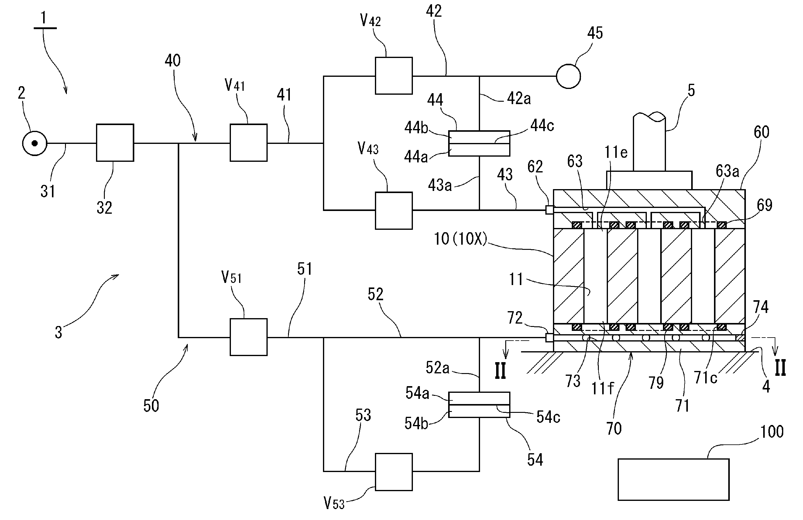
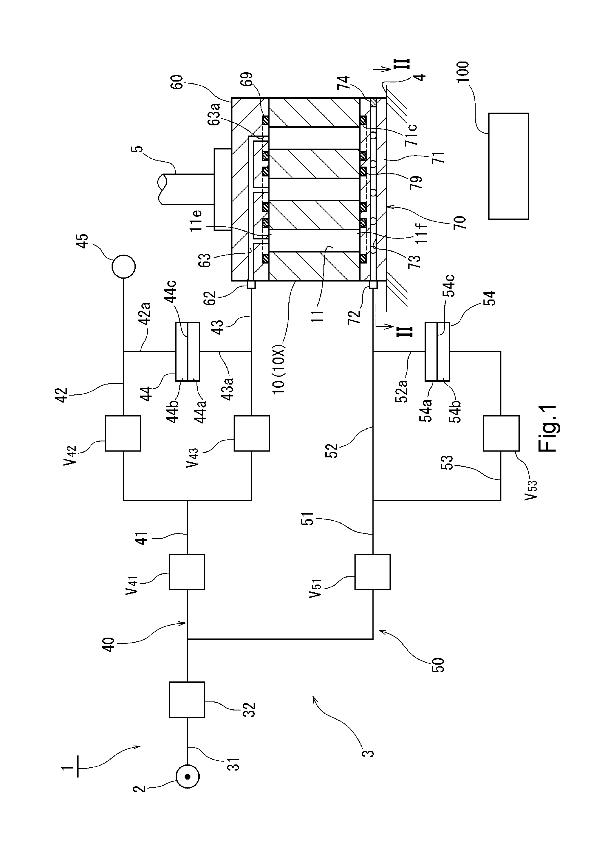
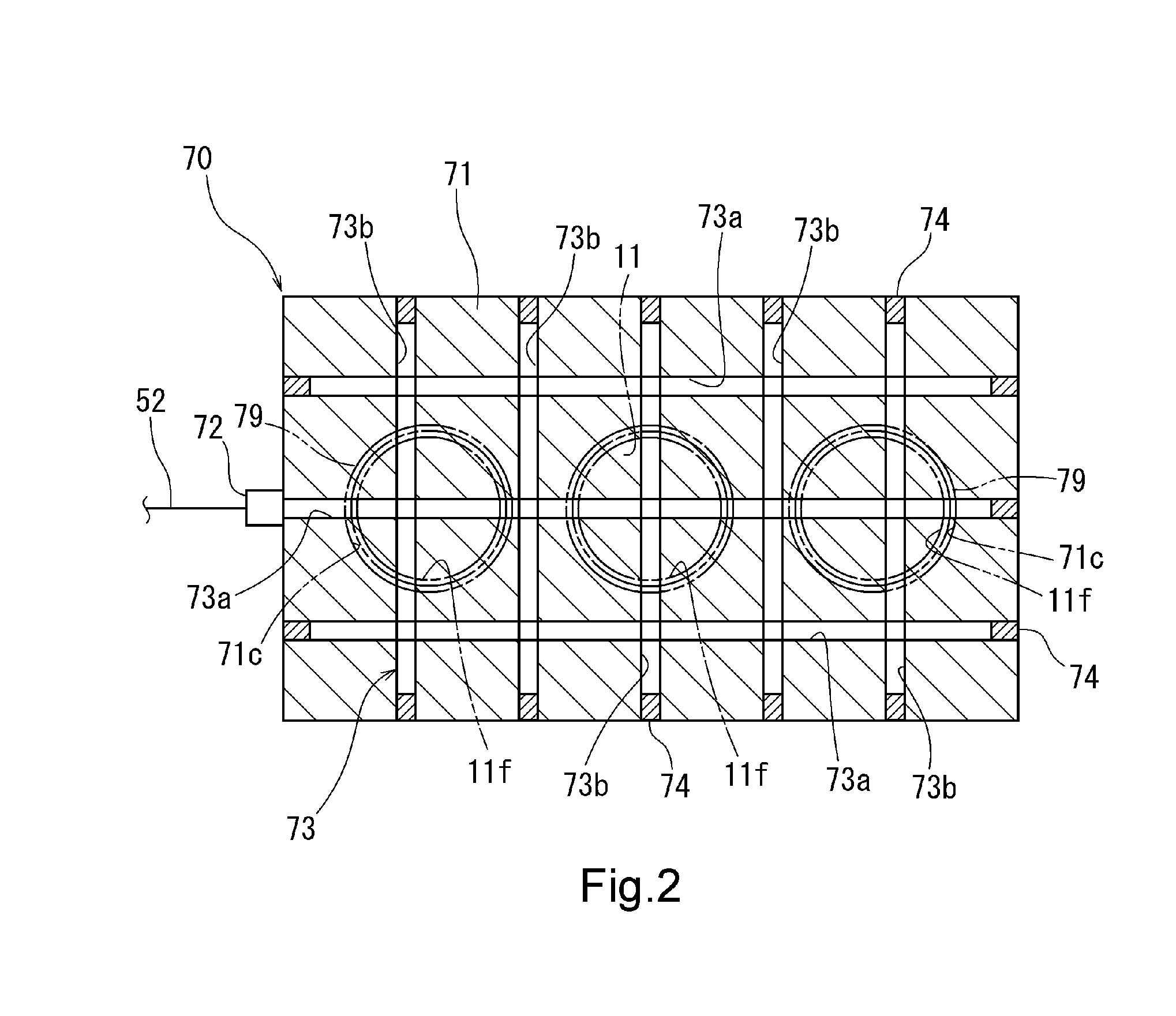
[0034]FIG. 1 schematically illustrates a circuit configuration of a leak testing apparatus 1 according to the present invention. A test object of the leak testing apparatus 1 is a workpiece 10. An example of the workpiece 10 is a cylinder block of an automotive engine. A plurality of inner spaces 11 are formed inside the workpiece 10. In this embodiment, all of the inner spaces 11 are open to an upper outer surface and a lower outer surface of the workpiece 10.
[0035]As shown in FIG. 1, the leak testing apparatus 1 has a pressurized gas source 2 and a pressurized gas passage 3. The pressurized gas source 2 is an air compressor. The pressurized gas source 2 can produce an air pressure in the order of some hundreds of kPa.
[0036]The pressurized gas passage 3 is constructed as follows:
[0037]A common passage 31 of the pressurized gas passage 3 extends from the pressurized gas source 2. A regulator 32 is provided in the common passage 31. The regulator 32 controls pressure in a portion of ...
second embodiment
[0086]For example, in a second embodiment shown in FIG. 3, an inner space 11A of the plurality of inner spaces 11 extends from an upper surface of the workpiece 10 but doesn't reach a lower surface of the workpiece 10. A lower end portion of the inner space 11A is distanced from the heat sensitive member 70. Therefore, it takes time for temperature change inside the inner space 11A to be transmitted to the heat sensitive member 70. On the other hand, the inner space 11A is located near one side surface 10a (surface in the right side in FIG. 3) of the workpiece 10.
[0087]Now, a temperature measuring device 80 is placed on the side surface 10a of the workpiece 10. The temperature measuring device 80 assists the heat sensitive member 70 in detecting temperature. The temperature measuring device 80 is a resistance thermometer. Although not shown in detail, a temperature measuring circuit is integrated in the temperature measuring device 80. The temperature measuring circuit has two (a pl...
third embodiment
[0094]In a third embodiment shown in FIG. 5, a pressure control valve V40 is disposed in the first introduction passage 40. Air pressure in the first introduction passage 40 can be controlled by the pressure control valve V40 and, consequently, introduction pressure to the inner spaces 11 can be controlled. A pressure control valve V50 is disposed in the second introduction passage 50. Air pressure in the second introduction passage 50 can be controlled by the pressure control valve V50 and, consequently, pressure inside the pressure chamber 73 can be controlled.
[0095]By the pressure control valves V40, V50, the inner pressure of the pressure chamber 73 and the inner pressure of the inner spaces 11 are controlled such that the inner pressure of the pressure chamber 73 is greater than the inner pressure of the inner spaces 11. For example, the inner pressure of the inner spaces 11 is controlled at 300 kPa and the inner pressure of the pressure chamber 73 is controlled at 500 kPa. In ...
PUM
 Abstract
Description
Claims
Application Information
 - R&D
- Intellectual Property
- Life Sciences
- Materials
- Tech Scout
- Unparalleled Data Quality
- Higher Quality Content
- 60% Fewer Hallucinations
Browse by: Latest US Patents, China's latest patents, Technical Efficacy Thesaurus, Application Domain, Technology Topic, Popular Technical Reports.
© 2025 PatSnap. All rights reserved.Legal|Privacy policy|Modern Slavery Act Transparency Statement|Sitemap|About US| Contact US: help@patsnap.com


