
Anti-lock hydraulic braking system, in particular for motorized two-wheel vehicles

a technology of anti-locking and hydraulic braking, which is applied in the direction of braking system, braking action transmission, transportation and packaging, etc., can solve the problems of preventing the use of such a braking system in particular in two-wheel vehicles with inexpensive materials, and the complexity of the device is required, so as to reduce the braking pressure, prevent a negative pressure, and improve the quality of control

Inactive Publication Date: 2012-06-26
FTE AUTOMOTIVE GMBH & CO KG
View PDF21 Cites 1 Cited by
  • Summary
  • Abstract
  • Description
  • Claims
  • Application Information

AI Technical Summary

Benefits of technology

The invention is a hydraulic braking system for motorized two-wheel vehicles that uses an auxiliary pressure circuit to control skid-controlled braking. The system eliminates the need for electromagnetically operated switching valves, reducing costs and complexity. The system uses the hydraulic pump to modulate pressure in the braking circuit, with a throttle device and volume equalization device to control the pressure. The system also includes a spring pressure reservoir for pressure modulation and a fixed baffle throttle for efficient pressure control. The hydraulic pump can be controlled using an electric motor, and the system is recommended for smaller vehicles due to its compact size and low weight.

Problems solved by technology

Although the above-described braking system is advantageously free of feedback on account in particular of the blocking effect of the inlet valve in the case of ABS control, i.e. the ABS pressure control shocks caused by the switching processes of the outlet valve are not transmitted to the main cylinder and thus the brake pedal, it is considered to be a disadvantage of this prior art that a relatively high device complexity is required which prevents the use of such a braking system in particular in inexpensive two-wheel vehicles.

Method used


Image

  • Anti-lock hydraulic braking system, in particular for motorized two-wheel vehicles
  • Anti-lock hydraulic braking system, in particular for motorized two-wheel vehicles
  • Anti-lock hydraulic braking system, in particular for motorized two-wheel vehicles

Examples


Embodiment Construction

OF EMBODIMENTS

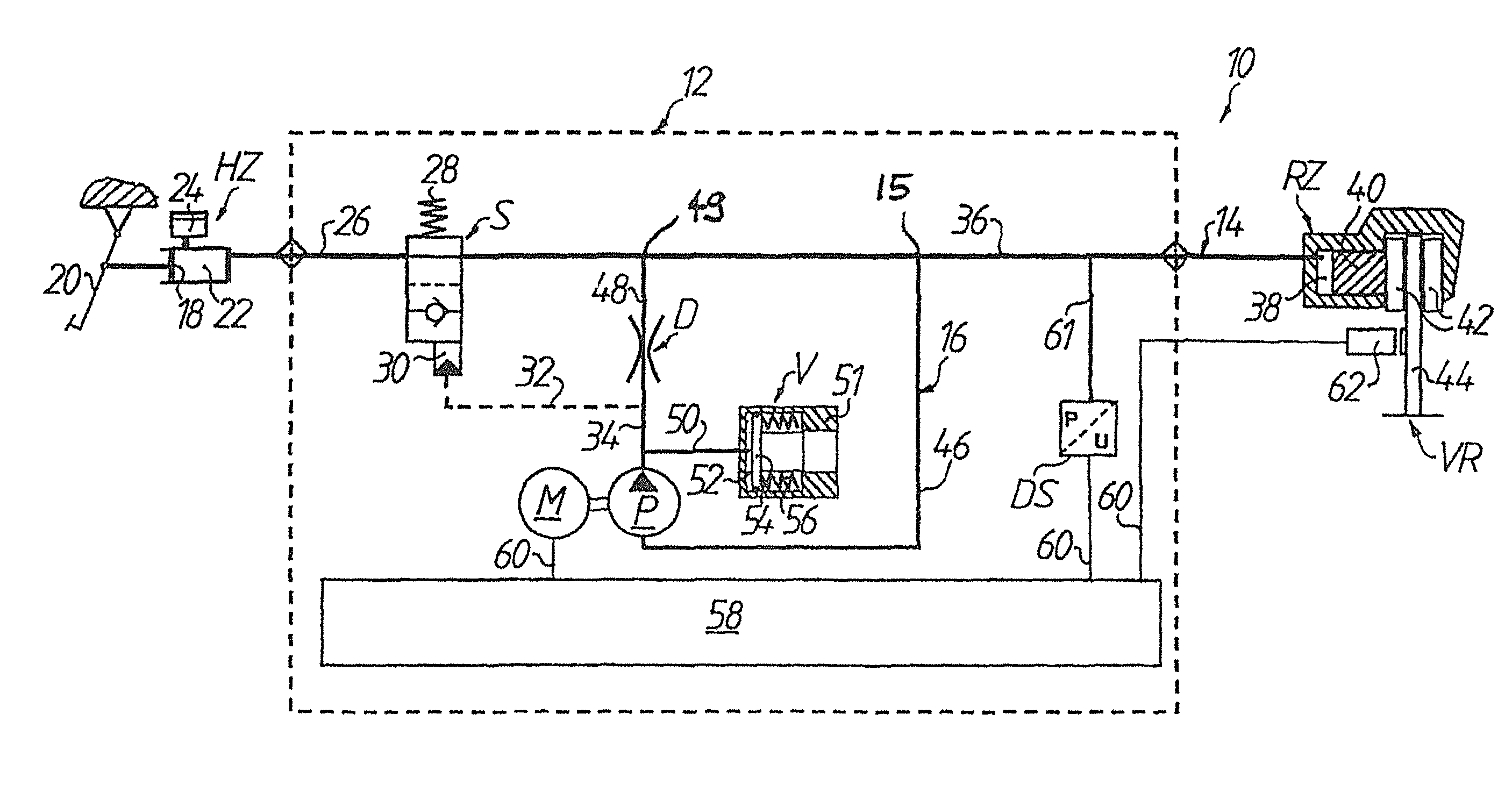
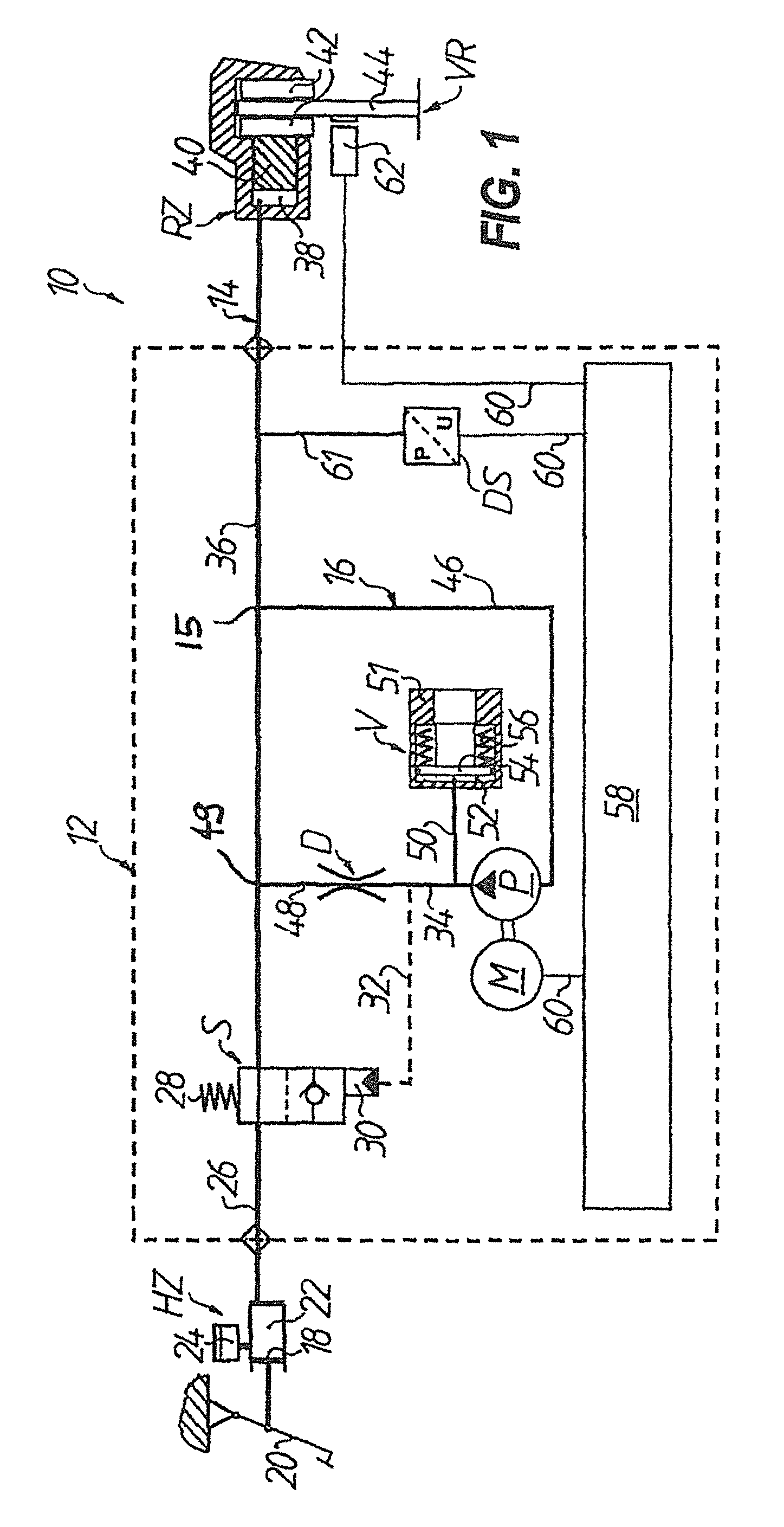
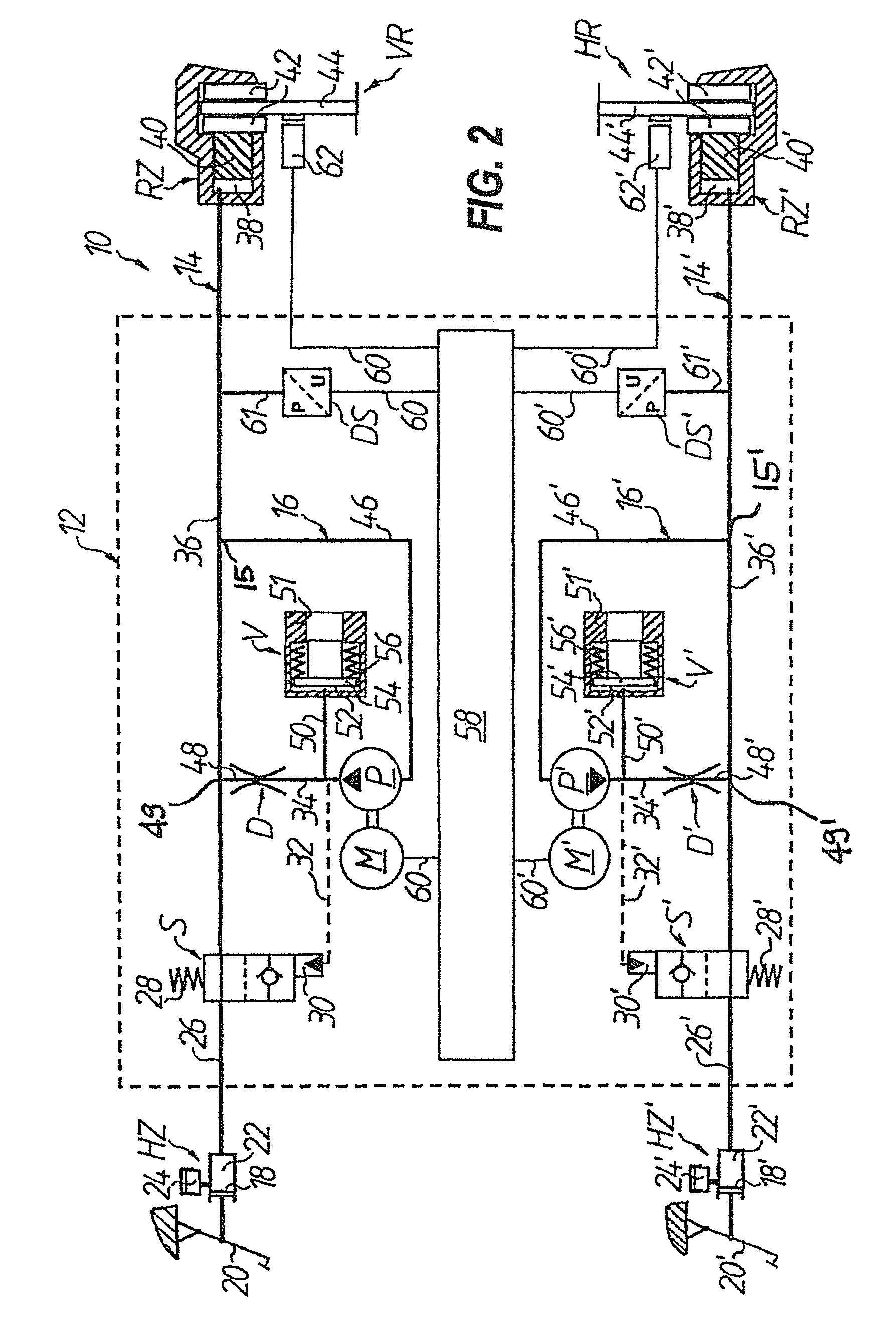
[0024]In FIG. 1, an anti-lock hydraulic braking system for a motorized two-wheel vehicle is generally denoted by 10, of which only the part of the system which acts on the front wheel VR is shown. The braking system includes a main brake cylinder HZ and a wheel brake cylinder RZ and also a pressure modulator which is connected therebetween and is generally denoted by 12. Seen hydraulically, the part of the braking system 10 which acts on the front wheel VR can be divided into a wheel brake circuit 14, which includes the main brake cylinder HZ, the wheel brake cylinder RZ and a switching valve S connected therebetween, and an auxiliary pressure circuit 16 which is connected in parallel from a first hydraulic connection point 49 to a second hydraulic connection point 15 between the switching valve S and the wheel brake cylinder RZ on the wheel brake circuit 14. The auxiliary pressure circuit 16 generally includes the first hydraulic connection point 49 located downstream...


PUM


Abstract

An anti-lock hydraulic braking system has a wheel brake circuit with a main brake cylinder, wheel brake cylinder and switching valve, and an auxiliary pressure circuit, connected in parallel between the switching valve and wheel brake cylinder on the wheel brake circuit. With ABS control, the switching valve can be switched from a basic position, where it hydraulically connects the main brake cylinder and wheel brake cylinder, to a switched position where it prevents a build-up of braking pressure on the wheel brake cylinder via the main brake cylinder, while the braking pressure on the wheel brake cylinder can be modulated by the auxiliary pressure circuit.

Description

TECHNICAL FIELD[0001]The invention relates to an anti-lock hydraulic braking system. In particular, the invention relates to an anti-lock hydraulic braking system for motorized two-wheel vehicles, as recently demanded by transport experts for safety reasons in general for motorized two-wheel vehicles.[0002]An anti-lock system, generally also known as an anti-lock braking system (ABS), in principle ensures that when, during a braking process with a braking pressure occurring on the wheel brake cylinder, a certain slowing threshold on the braked wheel is exceeded so that the wheel threatens to lock, the wheel braking pressure is reduced to below a second slowing threshold on this wheel. For this, it may be necessary to reduce the wheel braking pressure to zero. Thereafter, the wheel braking pressure is increased again until either the wheel is excessively braked again or the braking pressure defined by the driver is reached.PRIOR ART[0003]In the prior art, there is no lack of suggesti...

Claims


Application Information

Patent Timeline
Patent Type & Authority Patents(United States)
IPC IPC(8): B60T8/42
CPCB60T8/3225B60T8/4283
Inventor DRESCHER, WALTER
Owner FTE AUTOMOTIVE GMBH & CO KG
Learn More