Fixed abrasive wire
a technology of fixed abrasives and wires, which is applied in the direction of grinding devices, manufacturing tools, other chemical processes, etc., can solve the problems of contaminating the working environment, abrasives falling off, etc., and achieves the effect of small thickness, effective fixing of abrasives, and large thickness
- Summary
- Abstract
- Description
- Claims
- Application Information
AI Technical Summary
Benefits of technology
Problems solved by technology
Method used
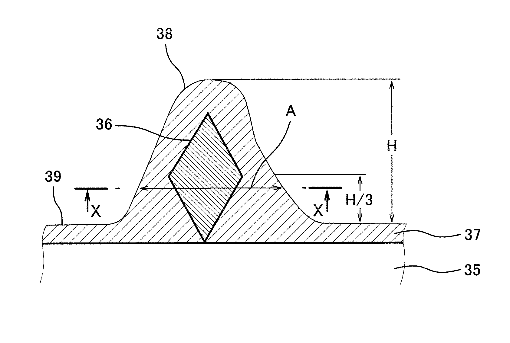
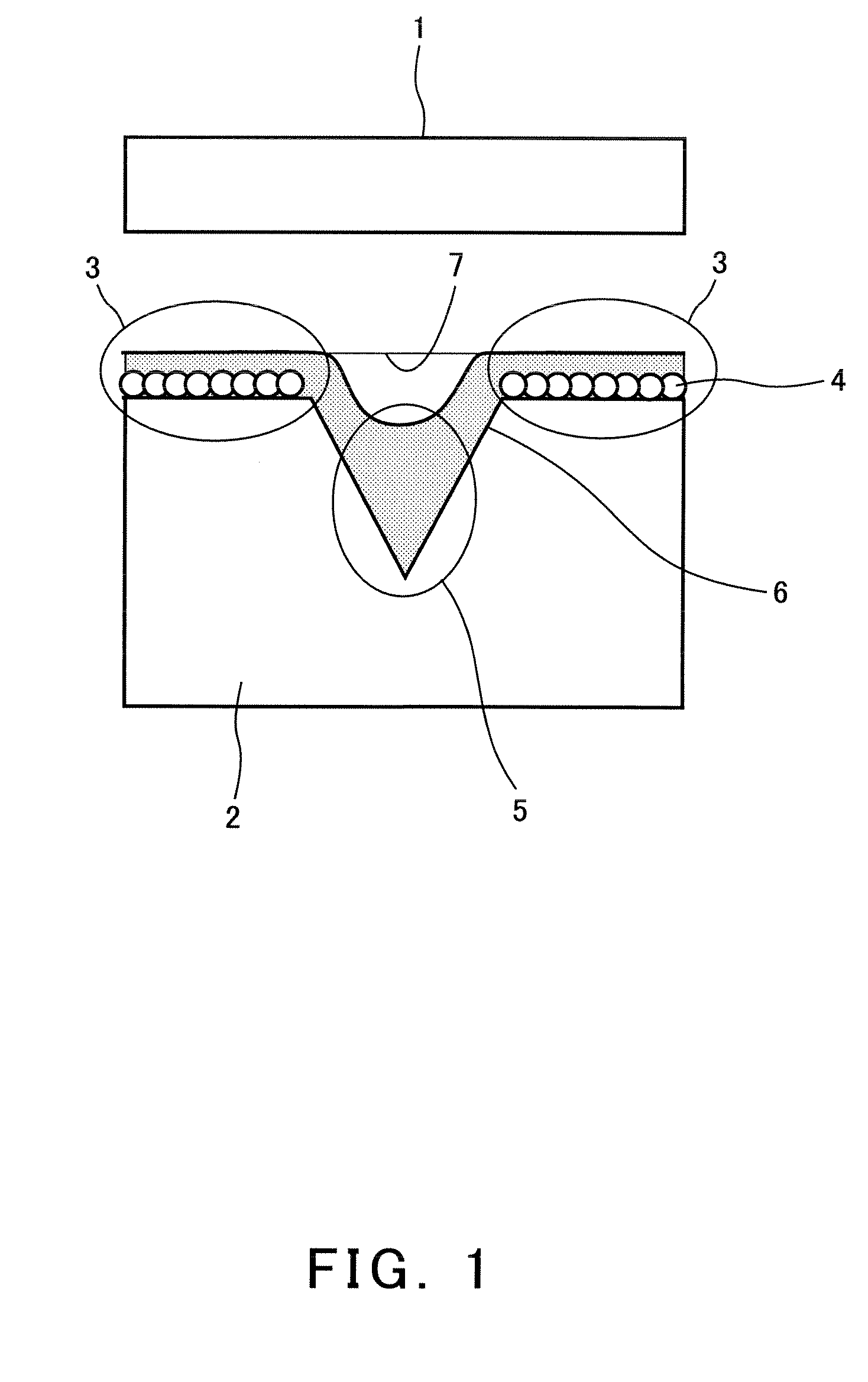
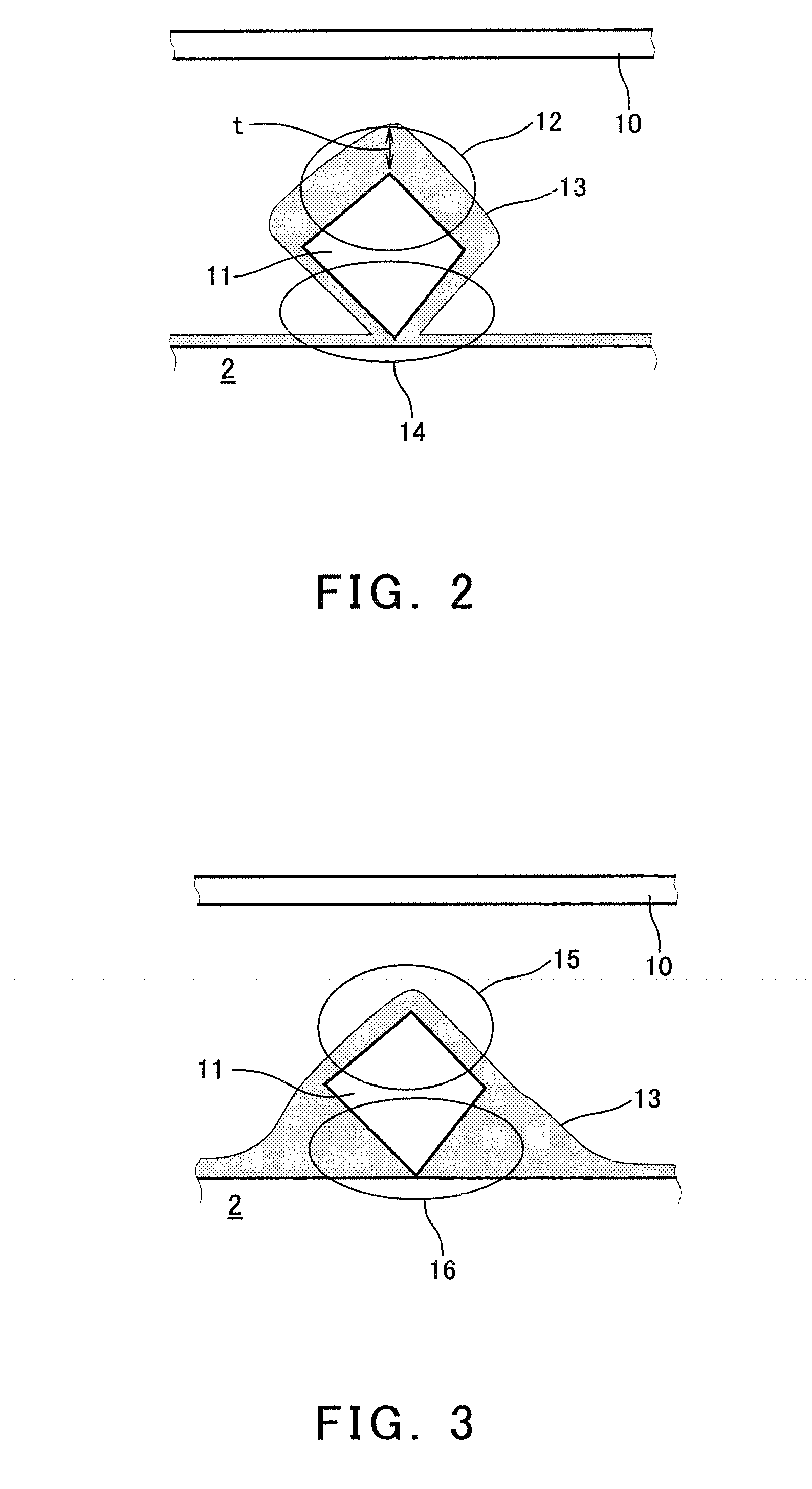
Image

Examples
example
[0064]Hereinafter, examples of the present invention will be described. However, the present invention is not limited to the examples below, but may be appropriately changed and modified without departing from the technical scope of the present invention.
(1) Production of a Fixed Abrasive Wire by Electroplating
[0065]A fixed abrasive wire was produced using plating equipment having a constitution schematically shown in FIG. 5. Specifically, a feed device 21 fed a steel wire 22 having a diameter of 160 μm. The steel wire 22 was subjected to alkaline cleaning at an alkaline cleaning tank (containing an alkaline degreaser of pH 11) 23, acid cleaning at an acid cleaning tank (containing sulfuric acid of pH 1) 24, rinsing with water at a rinse tank 25, and then pretreatment at a pretreatment tank (having a bath composition of pH 4.2 comprising nickel sulfamate 4-hydrate in an amount of 600 g / liter) 26. The steel wire 22 thus was nickel-plated to a thickness of 7 μm at a plating tank 27. T...
PUM
| Property | Measurement | Unit |
|---|---|---|
| diameter | aaaaa | aaaaa |
| diameter | aaaaa | aaaaa |
| diameter | aaaaa | aaaaa |
Abstract
Description
Claims
Application Information
 - R&D Engineer
- R&D Manager
- IP Professional
- Industry Leading Data Capabilities
- Powerful AI technology
- Patent DNA Extraction
Browse by: Latest US Patents, China's latest patents, Technical Efficacy Thesaurus, Application Domain, Technology Topic.
© 2024 PatSnap. All rights reserved.Legal|Privacy policy|Modern Slavery Act Transparency Statement|Sitemap