Targeting method, targeting device, computer readable medium and program element

a targeting device and computer readable medium technology, applied in applications, instruments, nuclear engineering, etc., can solve the problems of poor visualization of anatomical structures filled with air, poor visibility, and low signal quality in obese patients (subcutaneous fat)

Active Publication Date: 2012-06-26
KONINK PHILIPS ELECTRONICS NV
View PDF17 Cites 218 Cited by
  • Summary
  • Abstract
  • Description
  • Claims
  • Application Information

AI Technical Summary

Benefits of technology

[0011]The method may facilitate an efficient method for targeting and / or tracking of a first object which is inserted or injected into a second object under examination by observing the shape of the projected first object in a fluoroscopic image.
[0039]A method according to an exemplary embodiment of the invention may have the advantages that an entrance point (puncturing spot) into a body as well as an entrance angle into the body may be determinable during a medical procedure. Further, the needle position in the body may be determinable during the procedure and shutter positions may be set to reduce the patient dose during a CT acquisitions to monitor the progress of the procedure.

Problems solved by technology

However, this technique suffers from multiple drawbacks, poor visualization of anatomical structures filled with air, poor visibility when bony anatomy is superimposed on the structure of interest, low signal quality in obese patients (subcutaneous fat), for example.
The disadvantage of the technique is poor patient access and room sterility issues.
An intervention room equipped with a rotational X-ray device is much more suitable for such procedures, but for most of the procedures the contrast resolution of the X-ray device is not sufficient.

Method used


Image

  • Targeting method, targeting device, computer readable medium and program element
  • Targeting method, targeting device, computer readable medium and program element
  • Targeting method, targeting device, computer readable medium and program element

Examples


Embodiment Construction

[0047]The illustration in the drawings is schematically. In different drawings, similar or identical elements are provided with the similar or identical reference signs.

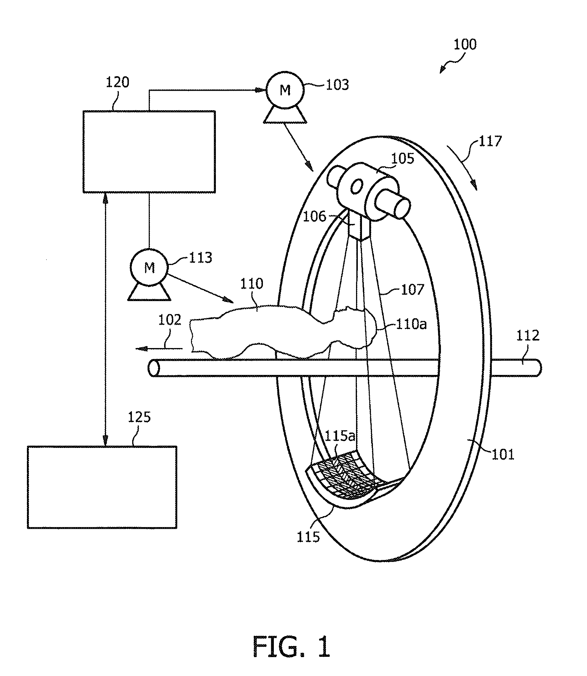
[0048]FIG. 1 shows an exemplary embodiment of a computed tomography scanner system which can be used in order to provide a three-dimensional image from which a slice can be selected. For the further targeting method a so-called C-arm device can be used which looks similar to the CT but comprises only a C-arm gantry, i.e. a gantry in form of a C, instead of a gantry, which is depicted in FIG. 1.

[0049]The computed tomography apparatus 100 depicted in FIG. 1 is a cone-beam CT scanner. The CT scanner depicted in FIG. 1 comprises a gantry 101, which is rotatable around a rotational axis 102. The gantry 101 is driven by means of a motor 103. Reference numeral 105 designates a source of radiation such as an X-ray source, which emits polychromatic or monochromatic radiation.

[0050]Reference numeral 106 designates an aperture ...


PUM


Abstract

According to an exemplary embodiment a targeting method for targeting a first object from an entry point to a target point in an object (110) under examination is provided, wherein the method comprises selecting a two-dimensional image (301) of the object under examination depicting the entry point (305) and the target point (303) and determining a planned path (304) from the entry point to the target point, wherein the planned path has a first direction. Furthermore, the method comprises recording data representing a fluoroscopic image of the object under examination, wherein the fluoroscopic image is recorded under a second direction so that a normal of the image coincide with the first direction and determining whether the first object is on the determined planned path based on shape and / or position of the projection of the first object in the fluoroscopic image.

Description

FIELD OF INVENTION[0001]The invention relates to a targeting method, a targeting device, a system, a computer readable medium and a program element, in particular to a method for targeting a first object from an entry point to a target point in an object under examination.TECHNICAL BACKGROUND[0002]Percuteneous targeting of various types of cervico-thoracal, abdominal and limb lesions is most frequently based on image guided interventional approach. There are several clinical procedures where this approach is applied: biopsies, chemical and thermal ablations, pain management procedures etc, for example. Two of the most frequently used imaging techniques for the image guidance are ultrasonic (US) based and computer tomography (CT) based. The US guided procedures are characterized by an interactive needle advancement monitoring and relatively good visualization of compact anatomical structures, e.g. bones. However, this technique suffers from multiple drawbacks, poor visualization of a...

Claims


Application Information

Patent Timeline
Patent Type & Authority Patents(United States)
IPC IPC(8): G06K9/00
CPCA61B19/52A61B6/4441A61B19/50A61B2018/2025A61B2019/507A61B2019/5289A61B2019/5293A61B90/36A61B2090/366A61B2090/364A61B34/10A61B2034/107
Inventor HOMAN, ROBERT JOHANNES FREDERIKBABIC, DRAZENKOMIELEKAMP, PIETER MARIATIMMER, JAN
Owner KONINK PHILIPS ELECTRONICS NV
Why Eureka
Try Eureka