
Wire rope for a tire

a technology of wire rope and tire, which is applied in the field of metal layered cables, can solve the problems of relatively low rigidity of the anchoring rubber, affecting the road behaviour of vehicles fitted with such tires, and difficulty in mounting and/or demounting tires, etc., and achieves the effects of improving the ability of tires, easy warping, and easy deformation

Active Publication Date: 2012-07-03
MICHELIN RECH & TECH SA
View PDF9 Cites 5 Cited by
  • Summary
  • Abstract
  • Description
  • Claims
  • Application Information

AI Technical Summary

Benefits of technology

"The invention is a new type of cable that can be used to improve the mounting ability and road behavior of tires. The cable has two layers of construction, with wires wound together in a helix at a specific pitch. This design allows the tire's beads to be more easily deformed and ovalized, which improves its mounting ability. The cable can be used as a reinforcing element for various products, such as tires, internal safety supports, and other ground contact systems for automobiles. The tires can be used for vehicles of different types and can also be used for reinforcing the bead zone of tires."

Problems solved by technology

Although this new tire bottom-zone architecture has yielded excellent results, in particular in terms of endurance, it has however been noted that the great rigidity of the beads could cause difficulties when mounting and / or demounting the tires, in particular during manual operations, this problem being particularly true for tires of large dimensions such as for example heavy-vehicle tires.
However, such an elongation is obtained at the cost of what is called a recovery annealing heat treatment, carried out at a low temperature of between 250° C. and Ac1 (temperature corresponding to a transformation of the crystalline structure of the steel), which has the disadvantage of being relatively complex and expensive.
It is however noted nowadays that a relatively low rigidity of the anchoring rubber can adversely affect somewhat the road behaviour of vehicles fitted with such tires, in particular under sports running conditions; this is the case in particular for top-of-range passenger vehicles, the user of which wishes to have a very high level of road behaviour, in all circumstances, without compromise on safety, in particular on the grip properties, nor on the life of the tires.

Method used


Image

  • Wire rope for a tire
  • Wire rope for a tire
  • Wire rope for a tire

Examples


Embodiment Construction

[0040]In the present description, unless expressly indicated otherwise, all the percentages (%) indicated are mass %.

II-1. Layered Cable 4+N

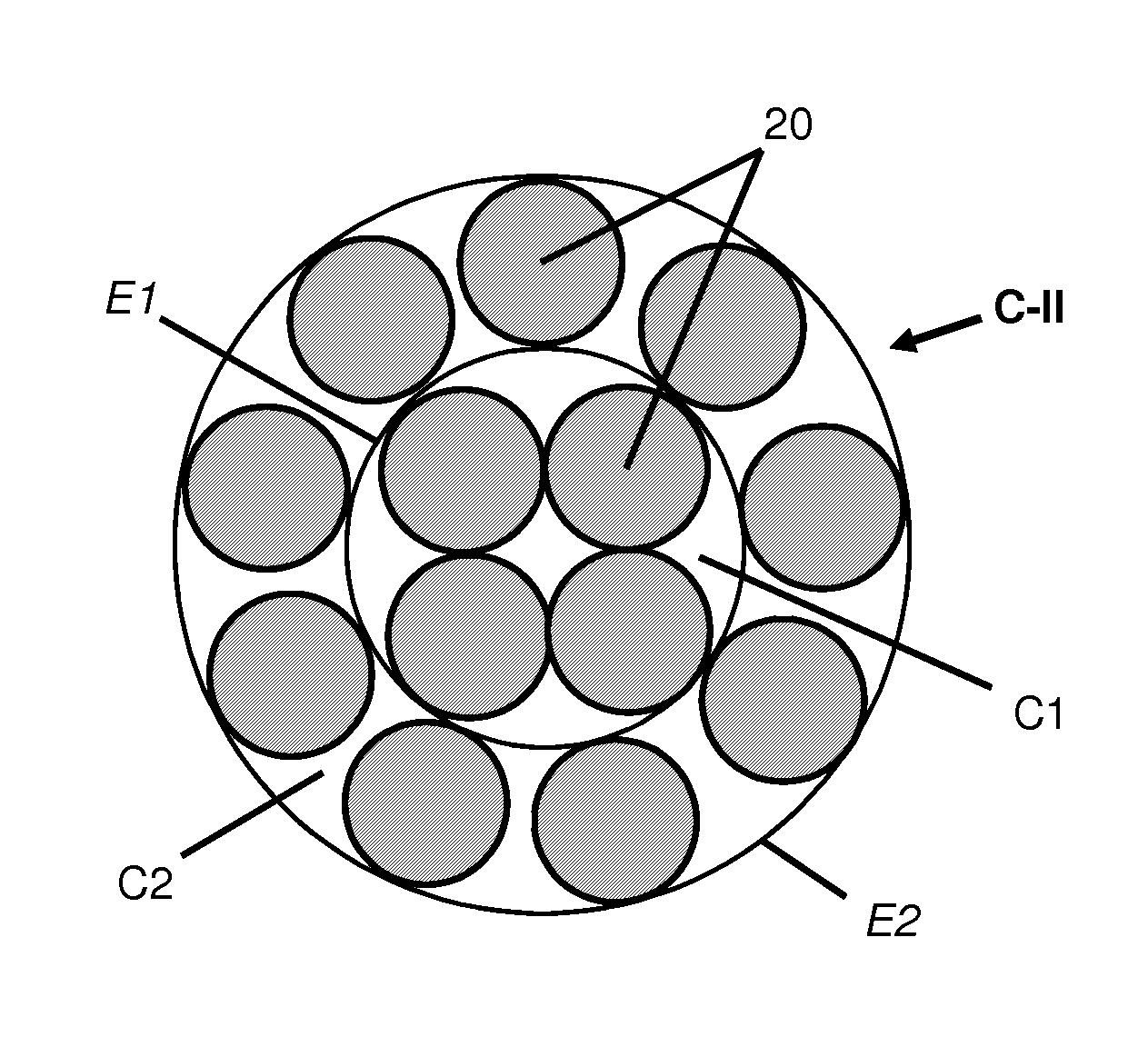
[0041]The metal cable according to the invention is a cable having two layers of construction 4+N comprising a core or inner layer (C1) of 4 wires of diameter d1 wound together in a helix at a pitch p1, this layer C1 itself being surrounded by an outer layer (C2) of N wires of diameter d2 wound together in a helix at a pitch p2, this cable furthermore having the following characteristics (d1, d2, p1 and p2 in mm):[0042]0.251[0043]0.252[0044]3.512

[0045]All the above characteristics are of course measured when the cable is at rest and its axis rectilinear.

[0046]“Metal cable” is understood here by definition to mean a cable formed of wires made majoritarily (that is to say to more than 50% of these wires) or fully (for 100% of the wires) of a metallic material.

[0047]The wires of layers C1 and C2 may have a diameter which is identical or different f...


PUM

PropertyMeasurementUnit
total elongation at breakaaaaaaaaaa

Abstract

Metal cable having two layers of construction 4+N comprising an inner layer C1 of 4 wires of diameter d1 wound together in a helix at a pitch p1, this layer C1 itself being surrounded by an outer layer C2 of N wires of diameter d2 wound together in a helix at a pitch p2, characterized in that said cable furthermore has the following characteristics (d1, d2, p1 and p2 in mm):0.25<d1<0.40;0.25<d2<0.40;3.5<p1<7<p2<14.Such a cable, of preferred construction 4+9, is in particular usable for reinforcing tires, in particular as an anchoring means for a carcass reinforcement of a tire without a solid bead wire.

Description

RELATED APPLICATION[0001]This application is a continuation of U.S. application Ser. No. 11 / 596,226 filed Feb. 14, 2008, which is the U.S. National Stage of International Application No. PCT / EP2005 / 005086 filed May 11, 2005, which claims priority from French Application No. 04 / 05162 filed May 12, 2004.FIELD OF THE INVENTION[0002]The present invention relates to metal layered cables usable for manufacturing tires, in particular for reinforcing their beads enabling these tires to be fixed to a vehicle wheel rim.BACKGROUND OF THE INVENTION[0003]Patent specification EP-A-582 196 was the first to describe a tire comprising a crown surmounted by a tread, a crown reinforcement, two sidewalls and two beads, a carcass reinforcement passing into the two sidewalls and anchored by means for anchoring in the beads, in which the carcass reinforcement comprises at least one circumferential alignment of reinforcing members (referred to as ‘radial’) oriented radially, arranged adjacently and practic...

Claims


Application Information

Patent Timeline
Patent Type & Authority Patents(United States)
IPC IPC(8): D02G3/48B60C15/04D07B1/06
CPCD07B1/062B60C15/04B60C15/0018D07B2201/2006D07B2201/2023D07B2201/2032D07B2201/2039D07B2201/2061Y10T428/12333D07B2205/3053D07B2501/2046D07B2205/3046D07B2801/10
Inventor BARGUET, HENRIPOTTIER, THIBAUDALVAREZ, DENISSIGNORET, CHRISTIAN
Owner MICHELIN RECH & TECH SA
Learn More