Tunable acoustical plaster system and method of making it

a technology of acoustical plaster and acoustical panels, applied in the direction of ceilings, solid waste management, flooring, etc., can solve the problems of difficult to find quiet interior spaces, not being accepted as providing an aesthetically pleasing appearance, and being seldom used in the main living area, so as to save raw materials and services, save time, and save costs

Active Publication Date: 2012-07-03
UNITED STATES GYPSUM CO
View PDF18 Cites 9 Cited by
  • Summary
  • Abstract
  • Description
  • Claims
  • Application Information

AI Technical Summary

Benefits of technology

[0012]Spaces where acoustical panels with a first finishing layer have been installed can achieve more or less sound attenuation by the addition of a second finishing layer. It would not be necessary to remove the acoustical panels and replace them with panels having different sound properties. This results in savings of time, the cost of raw materials and services in replacing the acoustical panels.
[0013]In newer construction, rather than having to stock a large number of acoustical panels of varying properties, the same panel could be used in more situations. The needs of particular areas could then be modified using the finishing layers. Cost savings of maintaining a large inventory of acoustical panels could be realized.

Problems solved by technology

Sounds of urban living can penetrate homes and offices, making it difficult to find quiet interior spaces.
Acoustical ceiling panels have been used for some time, but have not been accepted as providing an aesthetically pleasing appearance.
While these acoustical panels are popular for use in basement rooms and recreational areas, they are seldom used in main living areas as they are not considered to be as aesthetically pleasing as other finishing options.
Some sounds are also distorted, adding to the noise pollution problem.
Although this method produces the desired acoustical properties, it is extremely expensive and time consuming to replace plaster, wallboard or other acoustical panels with another wall system.

Method used


Image

  • Tunable acoustical plaster system and method of making it
  • Tunable acoustical plaster system and method of making it

Examples


example 1

[0034]A coating was prepared by combining the components of Table I in the amounts listed demonstrating the ability of our coating to tune the acoustical properties.

[0035]

TABLE ICOATING COMPOSITIONComponentTrade NameAmountPercentageRheologicalSuper Gel B56 g.2.3%ModifierColorantDCS ®13.6 g.0.5%StarchSTARPOL ® 1638.2g.0.3%BinderHP 41-830108 g.4.3%CarrierWater1988.6 g.79.1%FillerRYOLEX ® 39338.6 g.13.5%Perlite

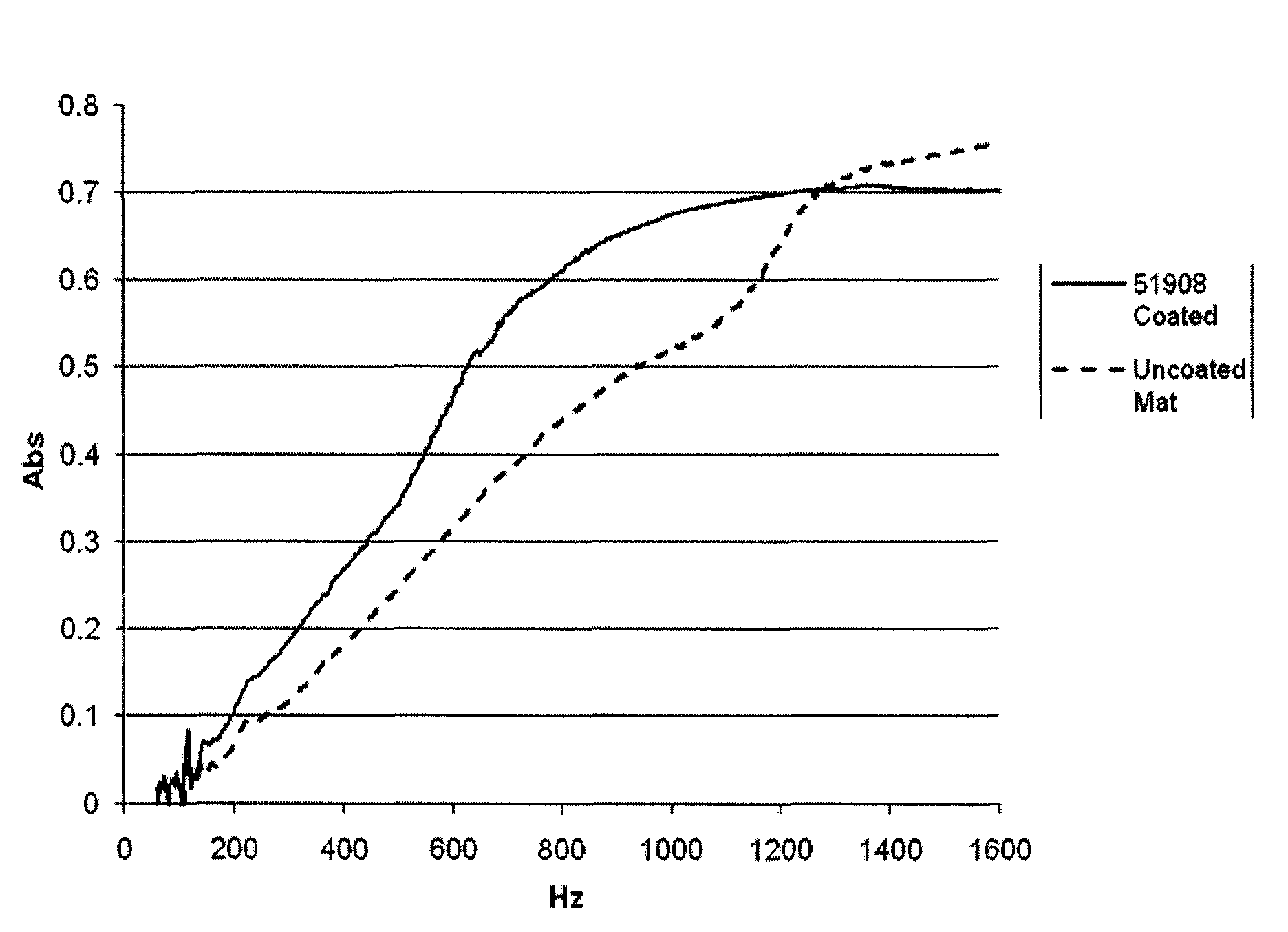
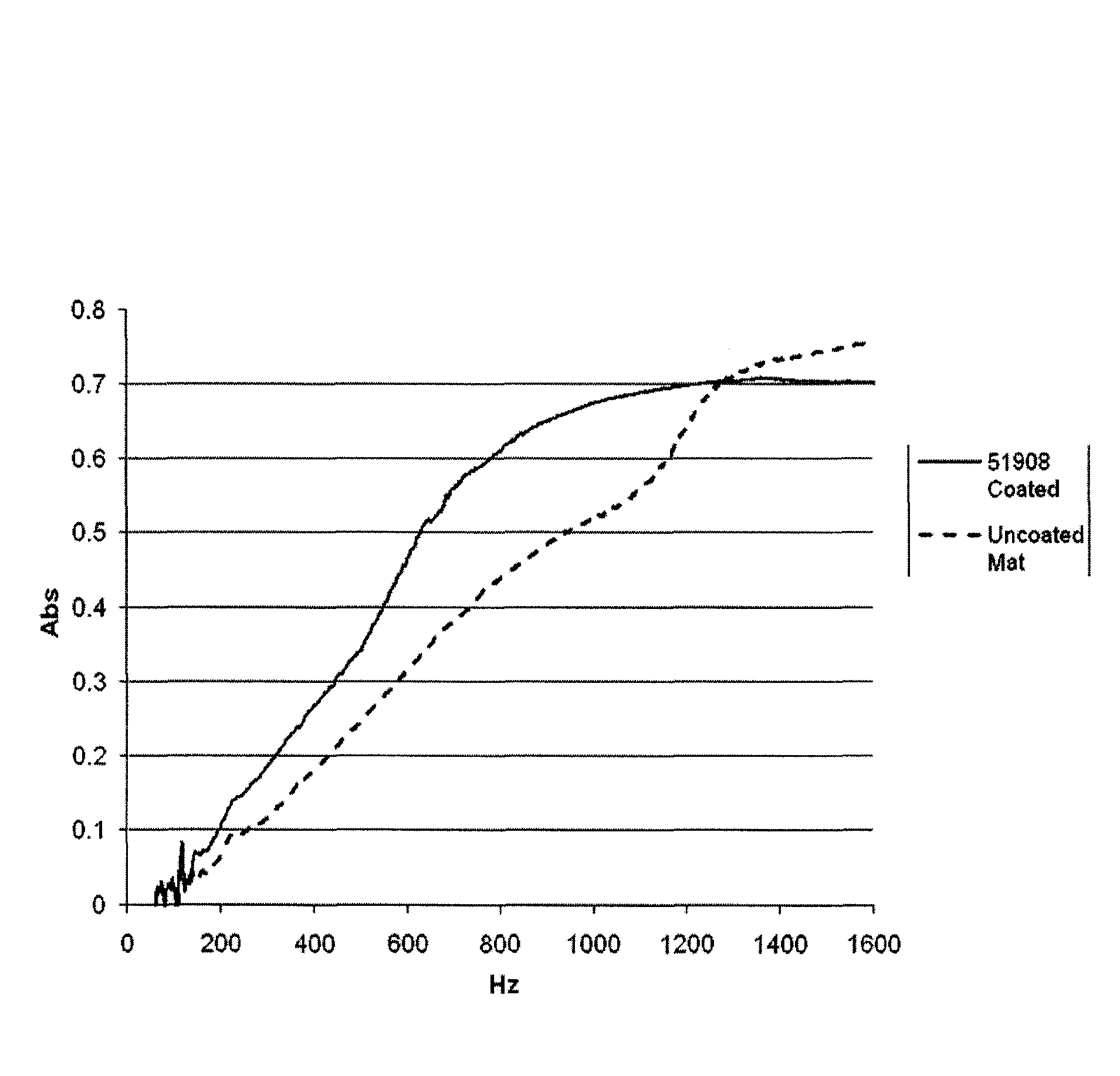
[0036]The coating was applied to the same mineral fiber basemat in subsequent layers as shown in Table II. The applied coatings were prepared by adding 130 g water to 1698 g of the coating of Table I. The first layer was applied to the basemat, resulting in a thin coating. This sample set is designated as Sample No. 061108B. A second coating was applied once the first coating was dried to produce the sample set designated as Sample No. 061108A. After the second coating was dried, a final coating was applied and the sample set designated as Sample No. 031108. The sound absorption ...


PUM

PropertyMeasurementUnit
particle size distributionaaaaaaaaaa
particle sizeaaaaaaaaaa

Abstract

A method of installing an acoustical system that provides a desired sound attenuation includes attaching an acoustical panel having a first density, a first porosity and a first void volume to the substrate. A first finishing layer is prepared with first particles, a first binder, a first rheological modifier and water which are combined, applied to the substrate and dried. The first finishing layer has a first density. When the first sound attenuation changes to a second sound attenuation a second finishing layer is prepared to include second particles, a second binder, a second rheological modifier and water. The dried second finishing layer has a second density. If the second density is less than the first density, the second sound attenuation is greater than the first sound attenuation. If the second density is greater than the first density, the second sound attenuation is less than the first sound attenuation.

Description

BACKGROUND[0001]Currently, there is a growing market for acoustical wall systems. Sounds of urban living can penetrate homes and offices, making it difficult to find quiet interior spaces. Noise pollution is an increasing problem and solutions are being sought that both reduce noise and produce an aesthetically pleasing appearance.[0002]Acoustical ceiling panels have been used for some time, but have not been accepted as providing an aesthetically pleasing appearance. The panels are often formed of a mineral wool composition that is very absorbent of sound. Finishing of the panels includes embossing or needling the panel surface, creating openings into which sounds enter. From the openings, a large fraction of the sound waves are absorbed by the mineral wool. While these acoustical panels are popular for use in basement rooms and recreational areas, they are seldom used in main living areas as they are not considered to be as aesthetically pleasing as other finishing options.[0003]C...

Claims


Application Information

Patent Timeline
Patent Type & Authority Patents(United States)
IPC IPC(8): E04B1/82
CPCC04B26/04E04B1/82C04B26/06E04F13/16C04B14/042C04B14/18C04B14/202C04B14/24C04B14/28C04B14/301C04B14/42C04B18/24C04B20/008C04B24/383C04B38/10Y10T29/49982C04B2111/00405C04B2111/00482C04B2111/00612C04B2111/0062C04B2103/54B32B9/00B32B2607/00Y02W30/91
Inventor YEUNG, LEE K.ALBARRAN, ENRIQUE L.
Owner UNITED STATES GYPSUM CO
Why Eureka
Try Eureka