Bi-metallic strip seal for a turbine shroud

Active Publication Date: 2012-07-03
FLORIDA TURBINE TECH
View PDF5 Cites 38 Cited by
  • Summary
  • Abstract
  • Description
  • Claims
  • Application Information

AI Technical Summary

Benefits of technology

[0009]It is an object of the present invention to provide for a strip seal which will be easy to install in the

Problems solved by technology

When the metal temperature changes, the metals expand/contract di

Method used


Image

  • Bi-metallic strip seal for a turbine shroud
  • Bi-metallic strip seal for a turbine shroud
  • Bi-metallic strip seal for a turbine shroud

Examples


Example

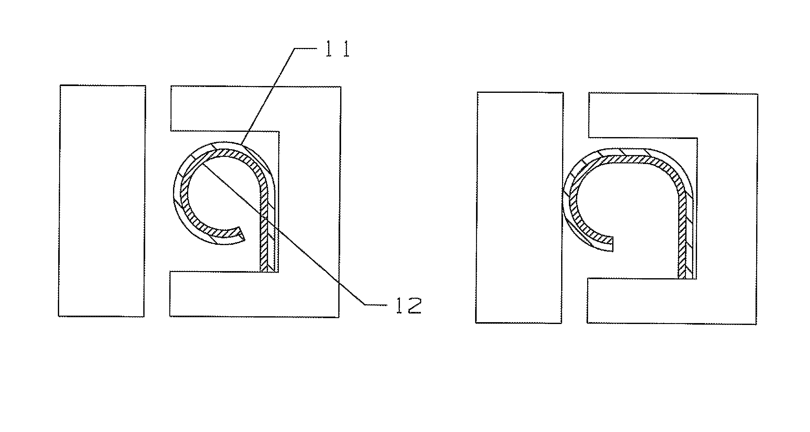
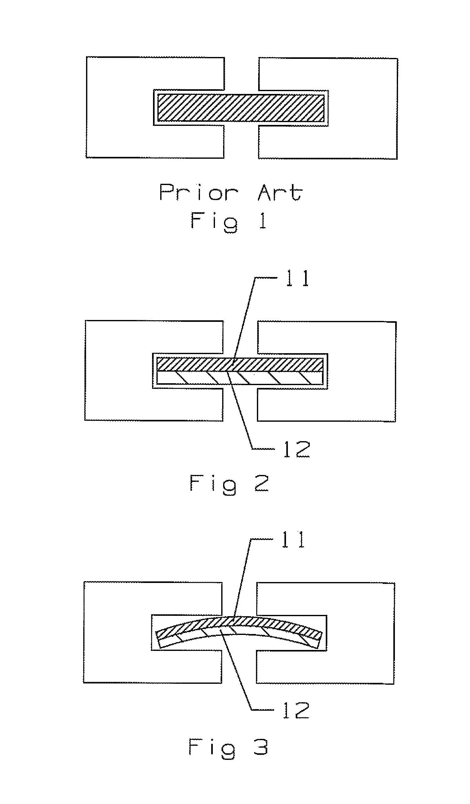
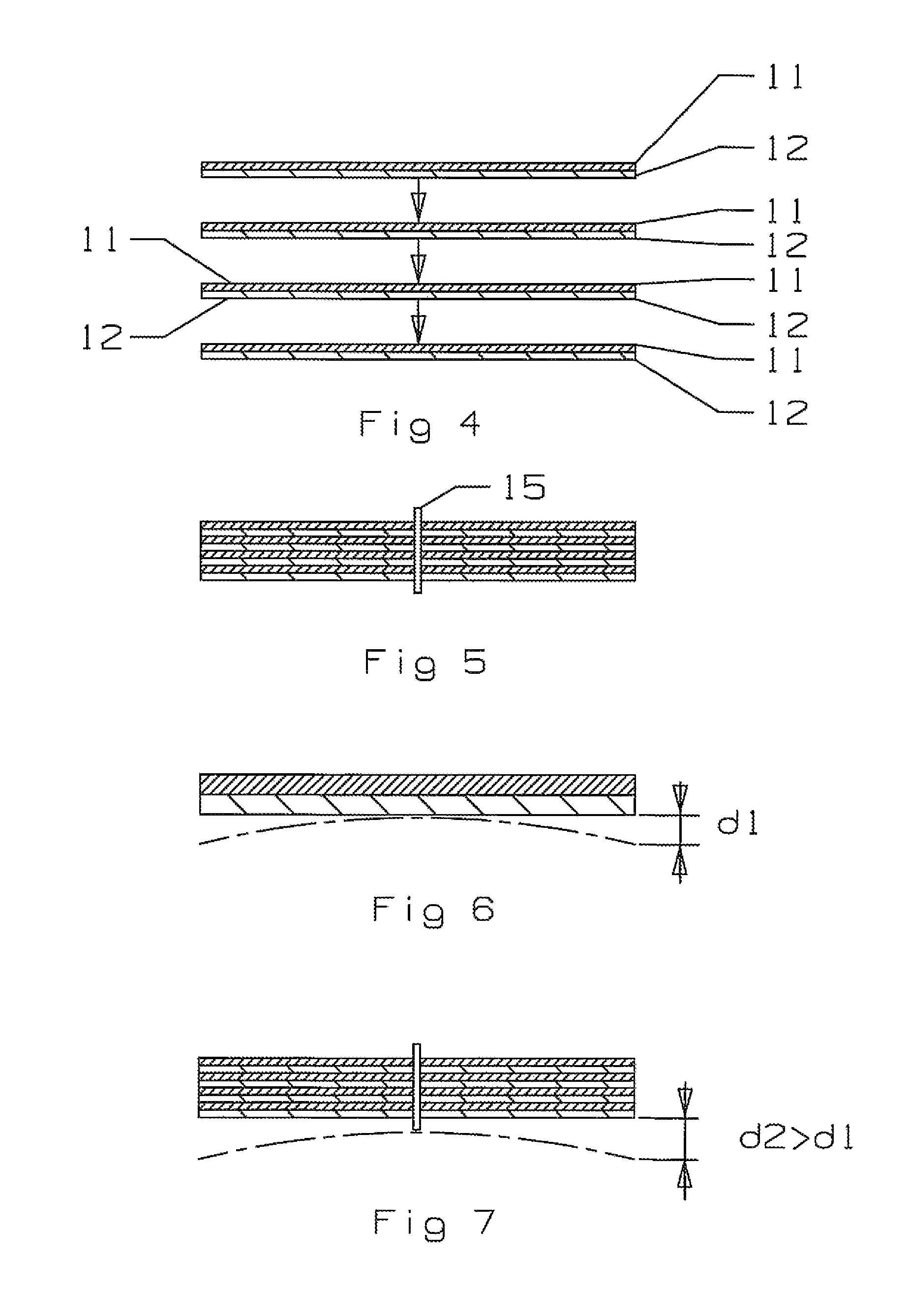
[0026]The present invention is a bi-metallic strip seal having one or more layers of bi-metallic stacks bonded together in the center and used to seal the slots in adjacent shroud segments of a gas turbine engine. The strip seals in a gas turbine engine must provide adequate sealing from engine startup (the cold condition or state), through the steady state condition, and through the engine shut down condition while maintaining the sealing capability all through these stages. The basic form of the bi-metallic strip seal of the present invention is shown in FIG. 2 in the cold condition. This seal is formed on one layer of bi-metallic materials that include a first metal 11 and a second metal 12 in which the coefficient of thermal expansion of the first metal 11 is greater than the coefficient of thermal expansion of the second metal 12. The two metals 11 and 12 are bonded together along the entire contacting surface.

[0027]The b-metallic strips are comprised of two metals with differe...


PUM


Abstract

A bi-metallic strip seal used to seal the gap between adjacent shroud segments in a gas turbine engine. The bi-metallic strip seal is formed from one or more layers of bi-metallic materials with different coefficients of thermal expansion. In a cold state the bi metallic strip seal will fit within the slot easily, while in the hot state the strip seal will expand to fit tightly within the slot and block leakage flow. The strip seal can be formed with the bi-metallic layers oriented similarly or oppositely in order to control the seal force and deflection properties. In one embodiment, the strip seal is formed from four bi-metallic layers in which the middle is bonded while the adjacent layers are free from shear.

Description

FEDERAL RESEARCH STATEMENT[0001]None.CROSS-REFERENCE TO RELATED APPLICATIONS[0002]None.BACKGROUND OF THE INVENTION[0003]1. Field of the Invention[0004]The present invention relates generally to a gas turbine engine, and more specifically to a strip seal between adjacent shroud segments of the turbine.[0005]2. Description of the Related Art including information disclosed under 37 CFR 1.97 and 1.98[0006]In a gas turbine engine, a compressed air from a compressor is burned with a fuel in a combustor to produce a hot gas flow. The hot gas flow is passed through a multiple stage turbine to convert most of the energy from the gas flow into mechanical work to drive the compressor, and in the case of an aero engine to drive a fan, and in the case of an industrial gas turbine (IGT) engine to drive an electric generator to produce electrical power.[0007]The turbine section of the engine is exposed to the high temperature gas flow. A plurality of stages of rotor blades and stator vanes react ...

Claims


Application Information

Patent Timeline
IPC IPC(8): F16J15/16
CPCF01D11/005F16J15/0806F16J15/0887F05D2240/11F05D2300/50212
Inventor RAWLINGS, CHRISTOPHER K
Owner FLORIDA TURBINE TECH
Why Eureka
Try Eureka