
Collection of electric power from renewable energy sources via high voltage, direct current systems with conversion and supply to an alternating current transmission network

a technology of electric power collection and high voltage, which is applied in the direction of electric power transfer ac network, dc source parallel operation, and conversion with intermediate conversion to dc, etc., which can solve the problems of significant contiguous area and solar pv power collectors

Active Publication Date: 2012-07-03
SCHNEIDER ELECTRIC USA INC
View PDF35 Cites 159 Cited by
  • Summary
  • Abstract
  • Description
  • Claims
  • Application Information

AI Technical Summary

Benefits of technology

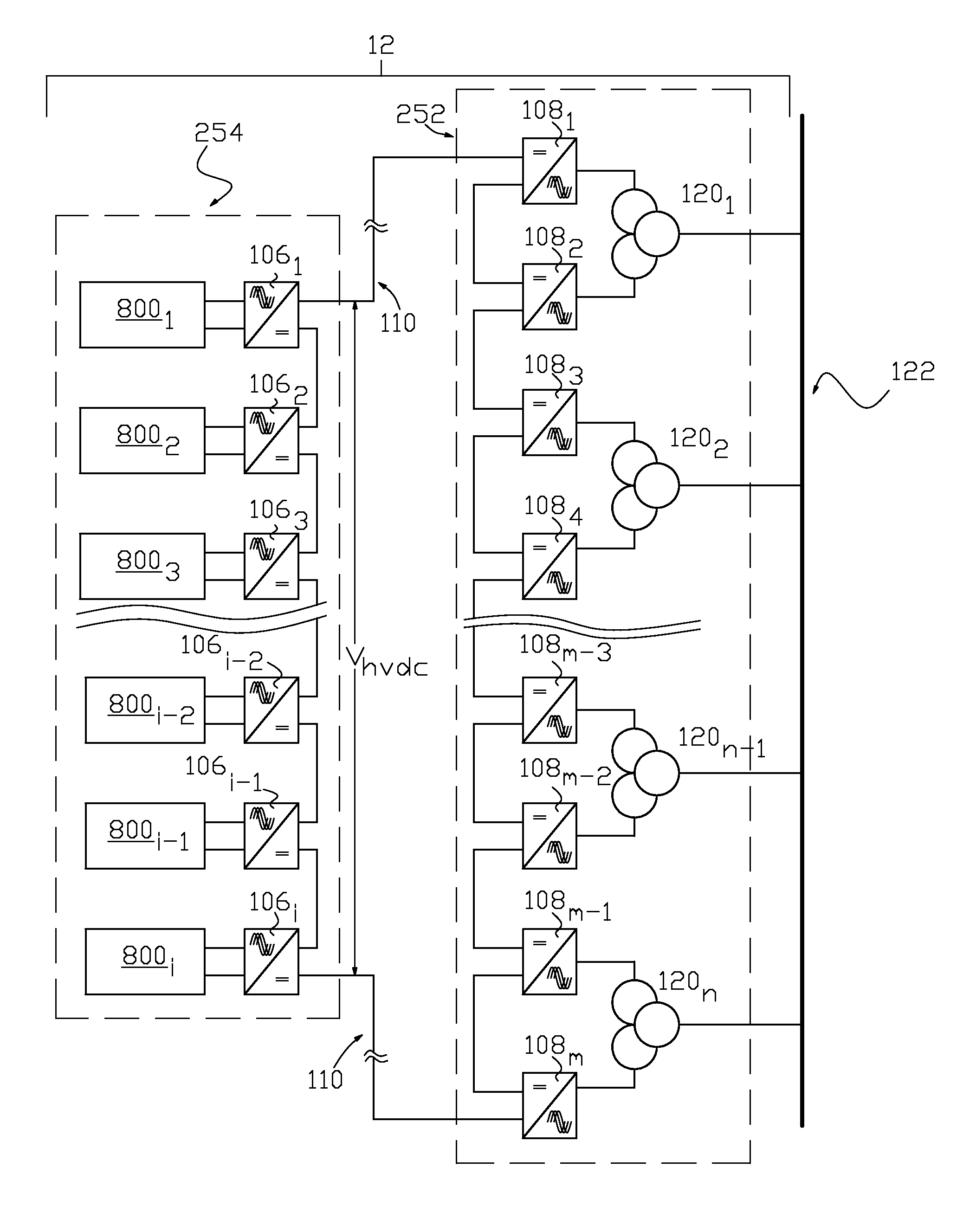
The present invention is about a system and method for collecting and delivering wind-generated electric power to an AC transmission network. The invention includes a high voltage DC source, such as a wind turbine, and a DC to AC inverter. The wind-generated electric power is collected from multiple collection nodes with each node having a high voltage DC output. The DC output is individually current regulated and combined to form a series string high voltage DC regulated current circuit. The DC regulated currents are then interconnected to form a series string inverter DC input circuit, which is connected to the AC transmission network. The invention also includes a combination of solar photovoltaic and wind-generated high voltage DC sources, with each source connected to a dedicated node isolated step-down current regulator. The technical effects of the invention include efficient collection and utilization of wind-generated electric power and a reliable and flexible source of energy for the AC transmission network.

Problems solved by technology

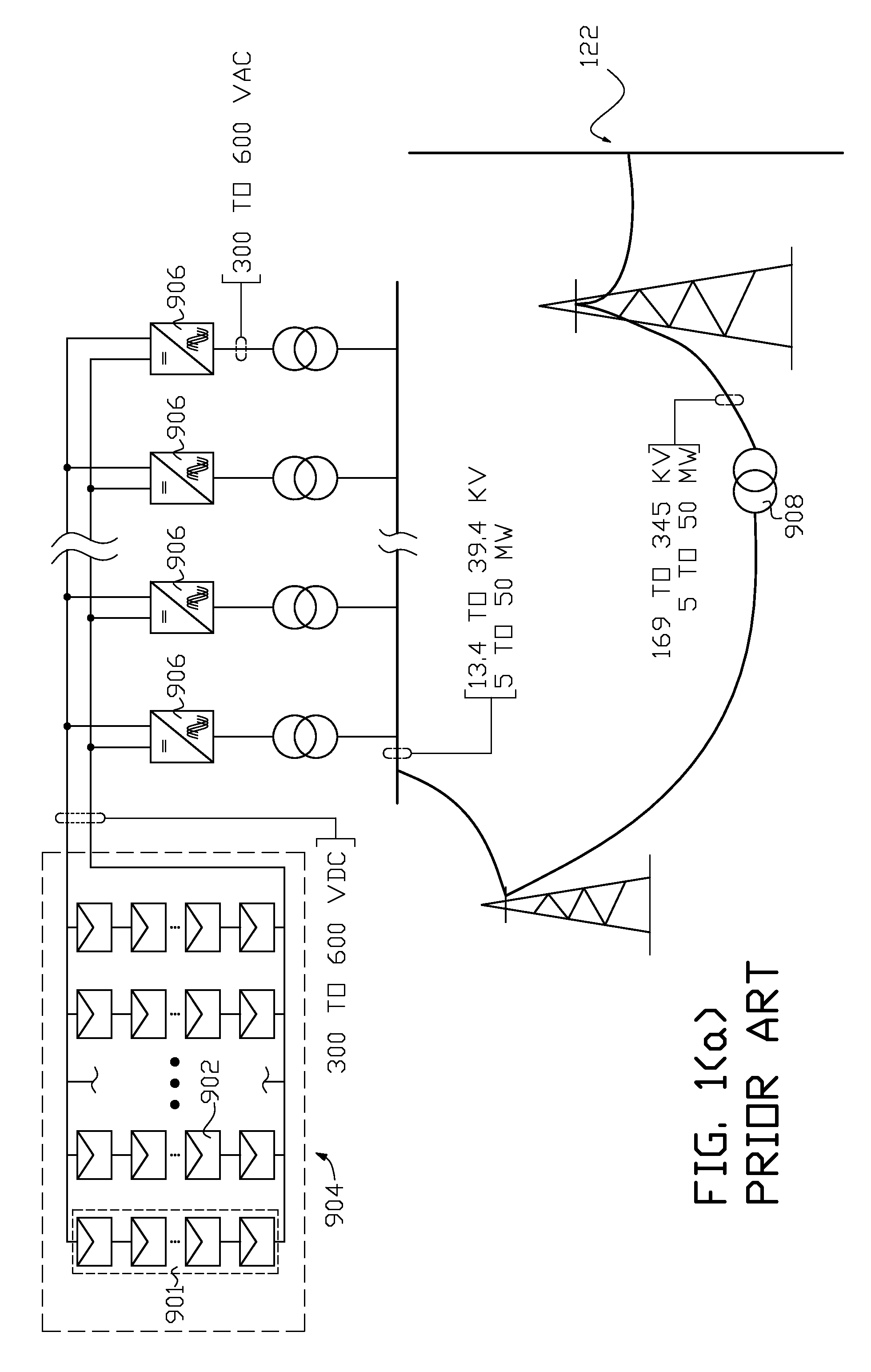
A disadvantage of the above conventional solar farm is that the large number of solar PV power collectors needed to collect a megawatt or greater quantity of DC electric power requires a significant contiguous area for mounting of the collectors.
Consequently sighting constraints for a typical megawatt or larger solar farm is a large contiguous area that is near the AC grid into which the converted DC power is to be injected.
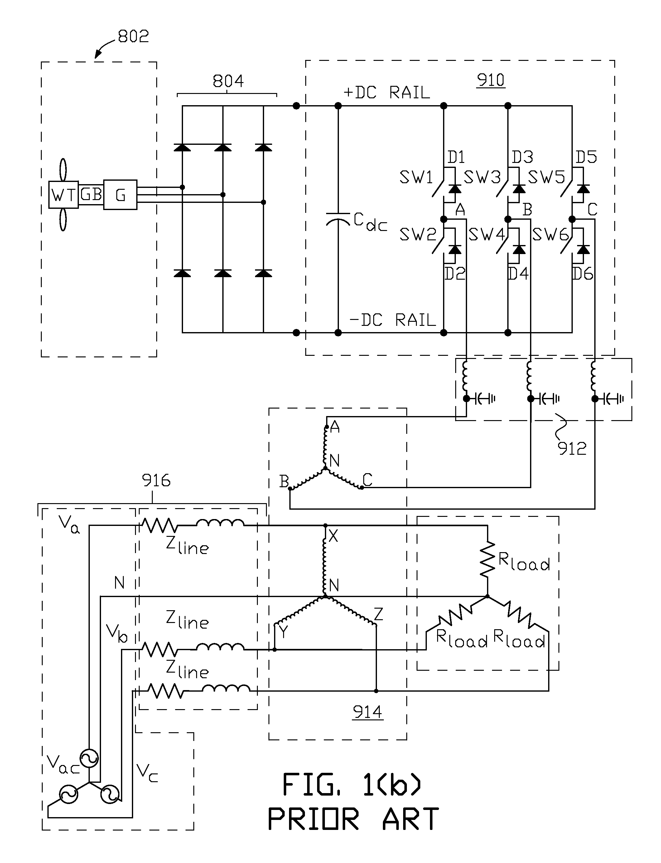
Typically a wind farm is located a significant distance from populated areas because of noise pollution due to low frequency air turbulence and mechanical vibrations from the wind turbine driven generator assembly, which means the wind farm may be located a significant distance from the AC grid into which the wind-generated power is injected.

Method used


Image

  • Collection of electric power from renewable energy sources via high voltage, direct current systems with conversion and supply to an alternating current transmission network
  • Collection of electric power from renewable energy sources via high voltage, direct current systems with conversion and supply to an alternating current transmission network
  • Collection of electric power from renewable energy sources via high voltage, direct current systems with conversion and supply to an alternating current transmission network

Examples


Embodiment Construction

[0043]FIG. 2 illustrates one example of an arrangement of apparatus 10 of the present invention for solar photovoltaic DC power collection, conversion to AC power, and supply of the AC power to a transmission network. Solar power collection nodes 1001 through 100i are each connected to a respective node-isolated step-down current regulator 1061 through 106i, where “i” is a positive integer. Each solar power collection node (generally referred to by reference number 100) comprises a plurality of solar PV power collectors 1021 through 102j having their DC outputs, Vcol, connected together in parallel as shown in FIG. 6. The variable “j” may be any positive integer, and can be a different integer value for the plurality of solar PV power collectors in each distinct solar power collection node 100. A typical solar PV power collector (generally referred to by reference number 102) is illustrated in non-limiting physical and electrical schematic form in FIG. 7 and FIG. 8 respectively. Ref...


PUM


Abstract

Wind-generated electric power is collected in a multiple nodal arrangement where the DC output current of each node can be held constant while the DC output node voltage is allowed to vary. The DC outputs from the wind-generated power collection nodes are connected together in series and fed to a plurality of regulated current source inverters via a high voltage DC transmission link. Each inverter converts input DC power into a three phase AC output. The AC outputs of the regulated current source inverters are connected to a phase shifting transformation network that supplies three phase electric power to a conventional AC electrical transmission system. Alternatively wind-generated and photovoltaic-generated electric power is commonly collected in a nodal arrangement and transported at high voltage DC to a plurality of regulated current source inverters for supply to the conventional AC electrical transmission system.

Description

CROSS-REFERENCE TO RELATED APPLICATIONS[0001]This application is a continuation-in-part of U.S. application Ser. No. 12 / 434,641 filed May 2, 2009, which claims the benefit of U.S. Provisional Application No. 61 / 140,839, filed Dec. 24, 2008, both of which applications are hereby incorporated by reference in their entirety.FIELD OF THE INVENTION[0002]The present invention relates to the collection of electric power from renewable energy sources via a high voltage (HV) direct current (DC) system, conversion of the DC power into alternating current (AC) power, and supply of the AC power to an electric power transmission network.BACKGROUND OF THE INVENTION[0003]Renewable electric energy sources include DC electric power sources, such as photovoltaic modules and wind turbine generators that are co-located and electrically interconnected in large numbers to form solar and wind farms or power plants.[0004]Typically megawatt and larger capacity solar photovoltaic (PV) power plants comprise a...

Claims


Application Information

Patent Timeline
Patent Type & Authority Patents(United States)
IPC IPC(8): H02M5/00H02M5/40
CPCH02J3/36H02M7/493H02J3/385H02J3/386H02M2001/0074Y02E60/60Y02E10/58Y02E10/763H02J2300/40H02J2300/28H02J2300/26H02J3/381Y02E10/56Y02E10/76H02J3/44H02M1/0074
Inventor FISHMAN, OLEG S.
Owner SCHNEIDER ELECTRIC USA INC
Learn More