
Power linkage assembly for a high efficiency internal explosion engine

a technology of power linkage and internal explosion, which is applied in the direction of machines/engines, connecting rod bearings, crankshafts, etc., can solve the problems of affecting the efficiency of rotary position, the worst combustion condition in relation to the mechanics of piston and crankshaft, and the inability to achieve rotary position most efficient, etc., and achieves the effect of compression volum

Inactive Publication Date: 2012-07-10
DF RESERVE LC
View PDF63 Cites 6 Cited by
  • Summary
  • Abstract
  • Description
  • Claims
  • Application Information

AI Technical Summary

Benefits of technology

"The present invention provides a piston-powered internal explosion engine for providing power output through a rotating crankshaft. The engine includes an engine block with power cylinders formed therein for receiving working pistons, bearing means for supporting the crankshaft, and a crankshaft supported within the bearing means. The IE engine is designed to maintain a constant peak compression ratio and to enhance mixing of air / fuel mixture as it is caused to displace in a dynamic manner. The technical effects of the invention include improved power output and efficiency, reduced emissions, and improved engine performance."

Problems solved by technology

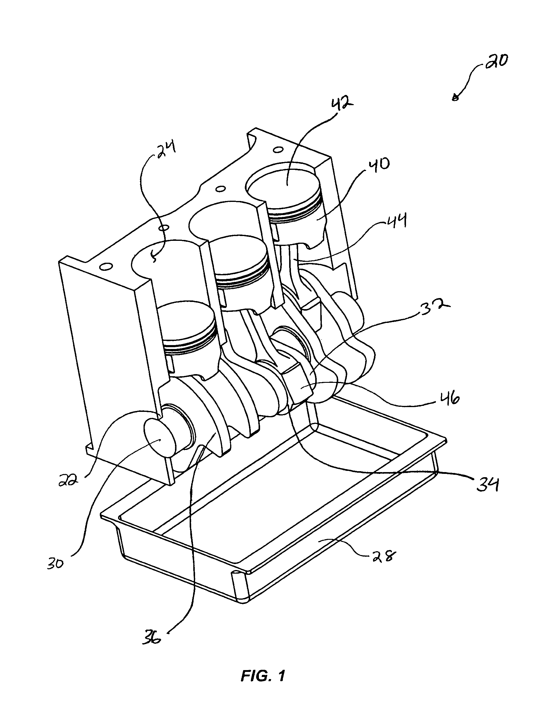
Most traditional internal combustion (“IC”) engines suffer from an inherent dichotomy, in that the engines are configured for conventional ignition of the air / fuel mixture with the piston(s) and crankshaft at a top-dead-center (“TDC”) position, Although this position results in the best condition for combustion, it is the worst condition for combustion in relation to the mechanics of the piston and crankshaft.
For many conventional IC engines, even though TDC is the best rotary position for combustion efficiency as compression ratios are at their peak, it is also the most inefficient rotary position mechanically because the crank and the connecting rod are momentarily aligned vertically at TDC so as to essentially “lock” the linkage where only a minimal amount of torque may be realized at that position.
Consequently, a significant portion of the potential (or available) energy generated at the time of combustion is unable to be applied as mechanical work, and is instead absorbed by the engine's cooling system or unnecessarily wasted and discharged as hot exhaust gases.
As a result of the extreme energy and power losses through the unrecovered heat, application of the IC engine's current four-stroke function with ignition at or near TDC notoriously yields largely unusable torque except in narrow RPM band widths.

Method used


Image

  • Power linkage assembly for a high efficiency internal explosion engine
  • Power linkage assembly for a high efficiency internal explosion engine
  • Power linkage assembly for a high efficiency internal explosion engine

Examples


embodiment 100

[0062]FIGS. 5a-5i together illustrate a series of sequenced, sectional views detailing the progression of the compression and power strokes of the representative IE engine described above. More specifically, FIGS. 5a-5i describe one representative embodiment 100 of the present invention for maintaining the compressed air / fuel mixture of a reciprocating-piston engine at a constant volume and at a desired (e.g., peak or something less than peak) and selective compression ratio through a range or plurality of crank 112 positions, and delaying detonation or ignition of the compressed air / fuel mixture until the working piston 120 has passed through the top dead center position and the engine crank has rotated to a more mechanically advantageous position that allows the resulting explosive reaction products to perform more work and generate additional torque, as compared with prior related IC engines, due to the rapid expansion of the combustion chamber.

[0063]The embodiment 100 of the IE ...

embodiment 200

[0098]Illustrated in FIGS. 14a and 14b is another representative embodiment 200 of the present invention for maintaining the compressed air / fuel mixture of a reciprocating-piston engine at a constant volume and at a given compression ratio, such as a peak compression ratio, through a range of crank positions, and delaying detonation of the compressed air / fuel mixture until the working piston has passed through the top dead center position and the engine crank has rotated to a more mechanically advantageous position that allows the resulting explosive reaction products to perform more work and generate additional torque.

[0099]Instead of using the floating piston and floating piston cylinder to perform a “switching” process, embodiment 200 of the IE engine can instead employ a unique power linkage 208, hereinafter known as a “CRAM power linkage” or “CRAM”, to maintain the compressed air / fuel mixture at a constant volume and at a peak compression ratio through a range of crank position...

embodiment 260

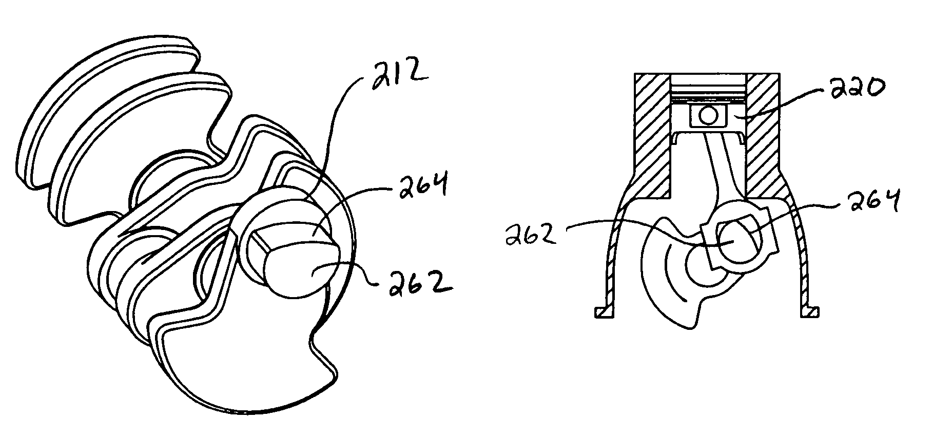
[0110]Illustrated in FIGS. 18a-18b is a representative embodiment 260 of the CRAM power linkage having a tangential / pitch cam surface formed on the lobe of the power crank or throw 112. The term “pitch” is due to the truncated shape 264 on the circular portion of the crankshaft lobe 262, and a corresponding truncated shape 268 on the circular portion of the bearing or bore 266 formed inside the crank-hub of the connecting rod 216. These truncated surfaces are positioned and mated to operate as a cam and a cam track, respectively. The cam surface 264 on the crankshaft lobe can be concentric and tangential with the geometric concentricity of the throw of the crankshaft, while the cam track surface 268 within the crank-hub end of the rod can be concentric and tangential with the geometric concentricity originating from the center of the piston-hub of the rod at its opposite end.

[0111]During operation of the tangential / pitch CRAM 260 (FIGS. 18c-18f), the cam 264 and cam track 268 surfac...


PUM


Abstract

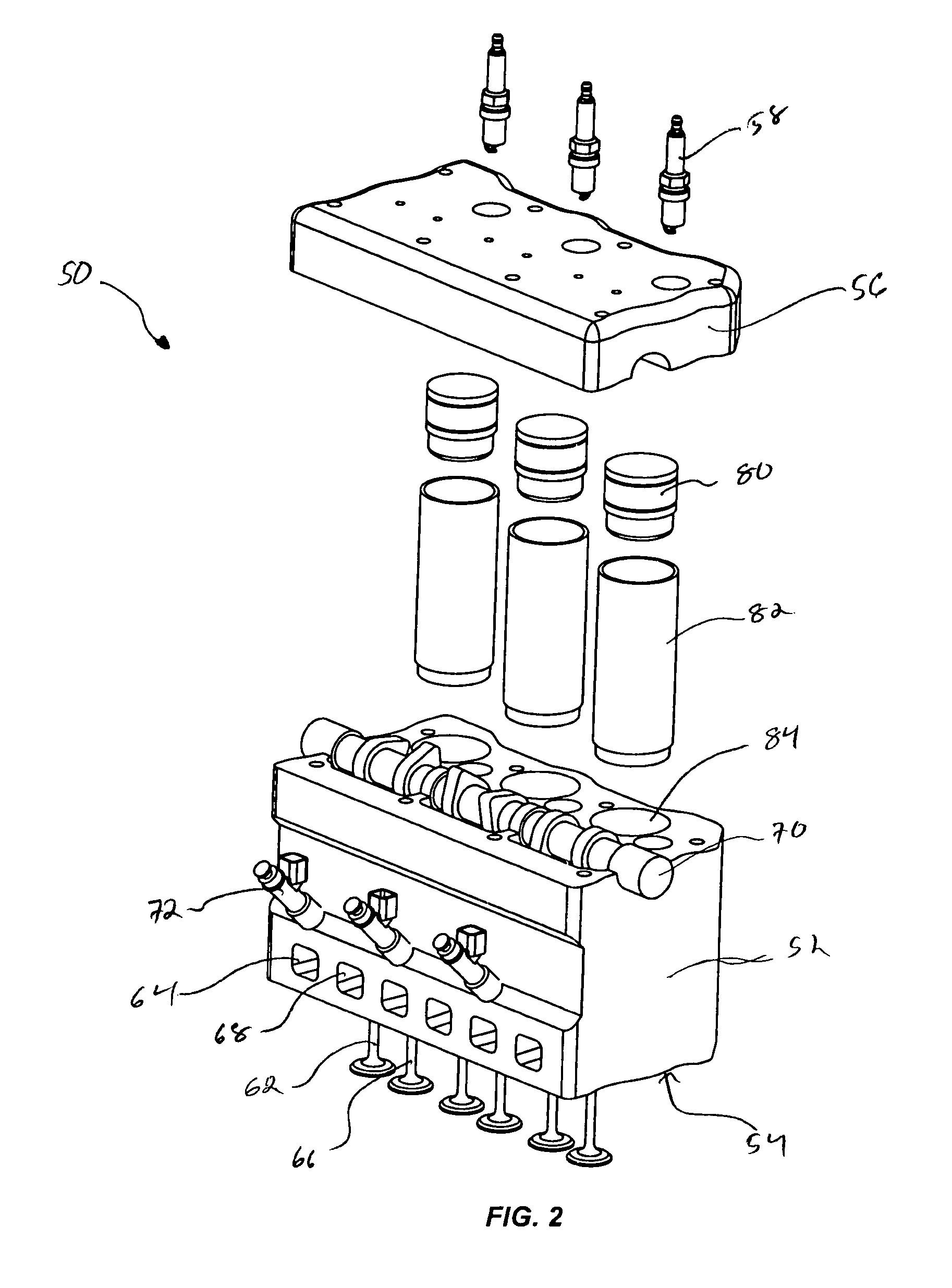
A four-stroke, piston-powered internal explosion (“IE”) engine for providing power output through a rotating crankshaft. The IE engine includes an engine block having power cylinders formed therein for receiving working pistons, bearing means for supporting the crankshaft, and a crankshaft supported within the bearing means having an output end extending outside of the engine block and a plurality of offset power cranks. The IE engine further includes connecting rods operably coupled to the power cranks and configured to transfer power from the working pistons to rotate the crankshaft, and working pistons that are received into the power cylinders and operably coupled to the power cranks. Each working piston has a head end positioned adjacent to a cylinder head to form a compression chamber and is configured to receive power from an explosion of a compressed volume of air / fuel mixture located within the compression chamber, and to transfer the received power to the connecting rods. The IE engine is further configured so that the compressed volume of air / fuel mixture is substantially constant, and a peak compression ratio is maintained, from an angular position of the rotating crankshaft of at least 20 degrees prior to a TDC position of a compression stroke, to an angular position of at least 20 degrees after the TDC position of a power stroke, and prior to detonation.

Description

RELATED APPLICATIONS[0001]This application claims priority to U.S. Provisional Application No. 61 / 067,638, filed Feb. 28, 2008, and entitled “High Efficiency Internal Explosion Engine”, which application is incorporated by reference in its entirety herein.FIELD OF THE INVENTION[0002]The field of the invention relates generally to reciprocating-piston engines, namely internal combustion engines, and more specifically to reciprocating-piston internal explosion engines.BACKGROUND OF THE INVENTION AND RELATED ART[0003]Most traditional internal combustion (“IC”) engines suffer from an inherent dichotomy, in that the engines are configured for conventional ignition of the air / fuel mixture with the piston(s) and crankshaft at a top-dead-center (“TDC”) position, Although this position results in the best condition for combustion, it is the worst condition for combustion in relation to the mechanics of the piston and crankshaft. In terms of the physics or the chemistry of hydrocarbon combust...

Claims


Application Information

Patent Timeline
Patent Type & Authority Patents(United States)
IPC IPC(8): F02B75/32F16C7/02F16C3/04
CPCF02D15/04F16C3/06F16C3/22F16C7/023F02B75/042F02B2075/027Y10T74/2173Y02T10/12Y10T74/2162Y10T74/2142Y10T74/2183F02B19/06F02B75/26F02B75/40F16C3/18F02B75/02F02B75/32
Inventor FURR, DOUGLAS K.
Owner DF RESERVE LC
Learn More