Method and device for generating diffusive gradients in a microfluidic chamber

a microfluidic chamber and diffusive gradient technology, applied in the field of microfluidics, can solve the problems of cell exposure to convective flow, fluid flow is not well suited to analyze non-chemotaxis, and all of them have limitations

Active Publication Date: 2012-07-10
THE UNITED STATES OF AMERICA AS REPRESENTED BY THE SECRETARY OF THE COMMERCE
View PDF11 Cites 16 Cited by
  • Summary
  • Abstract
  • Description
  • Claims
  • Application Information

AI Technical Summary

Benefits of technology

[0012]In a first aspect, the present invention provides a microfluidic system comprising a chamber defining an interior region adapted for retaining a liquid. The system also comprises at least three channels adapted to contain and direct liquid when flowing therethrough. Each channel defines an inlet and an outlet. Each of the channels is in fluid communication with the chamber via a respective access port located between the inlet and outlet of the respective channel. The system further comprises at least one flow controller for matching flow rates of liquid flowing in the channels. The system is free from membranes disposed at or proximate the access ports that would otherwise affect fluid communication between a respective channel and the chamber.
[0013]In another aspect, the present invention provides a microfluidic system comprising a chamber defining an interior region adapted for retaining a liquid. The system also comprises at least three channels adapted to contain and direct liquid when flowing therethrough. Each of the channels is in fluid communication with the chamber via a respective access port. Each channel defines an inlet and an outlet and all outlets are in fluid communication with one another at a junction. And, each of the channels defines an outlet leg extending between a respective access port and the junction. The system is free from membranes proximate the access ports that would otherwise affect fluid communication between a respective channel and the chamber.
[0015]In still another aspect, the present invention provides a method for analyzing microorganisms in the presence of a concentration gradient of an agent. The method comprises providing a microfluidic system comprising (i) a chamber and (ii) a plurality of channels, each channel being in constant fluid communication with the chamber via an aperture. The method also comprises filling the chamber with liquid. The method further comprises introducing the microorganisms into the chamber. And, the method additionally comprises flowing liquid and agent through at least one of the channels whereby at least a portion of the agent is diffusively transferred through the aperture into the chamber thereby forming the concentration gradient, and enabling analysis.

Problems solved by technology

However, a disadvantage of this practice is that cells may be exposed to convective flows which cells may not experience in-vivo.
In general, fluid flow is not well suited to analyze chemotaxis of non-adherent cells because instead of flushing soluble signals over the cells, it may flush both signals and cells.
Although each of these elegant approaches has provided valuable insight into chemotaxis, all of them have limitations.
Typically they (i) allow only for the diffusion between two solutions (one dimensional); (ii) are static; i.e., once the diffusive interface is established, it can only be modified using convective flows that inevitably disrupt the diffusion profiles; (iii) can operate only for short periods of time; or (iv) have difficult accessibility, in that cells need to be introduced in the chambers before the gradients are generated.
However, these previous efforts have suffered from one or more of the previously noted disadvantages.
As noted, such membranes interfere with extent and rate of diffusion of agents into the chamber.
Although satisfactory in certain respects, using one or more valves to selectively create such a liquid interface introduces additional variables which may deleteriously affect gradient development and maintenance.
Furthermore, requiring the use of moving components in a microfluidic system increases complexity and cost of the system.
Moreover, pressure differences between liquids on opposite sides of the valve and opening or closing operations of the valve itself can introduce or generate undesirable convective flows.
However, gels as a result of their high viscosity, are often not appropriate for many investigations.

Method used


Image

  • Method and device for generating diffusive gradients in a microfluidic chamber
  • Method and device for generating diffusive gradients in a microfluidic chamber
  • Method and device for generating diffusive gradients in a microfluidic chamber

Examples


embodiment devices

Preferred Embodiment Devices

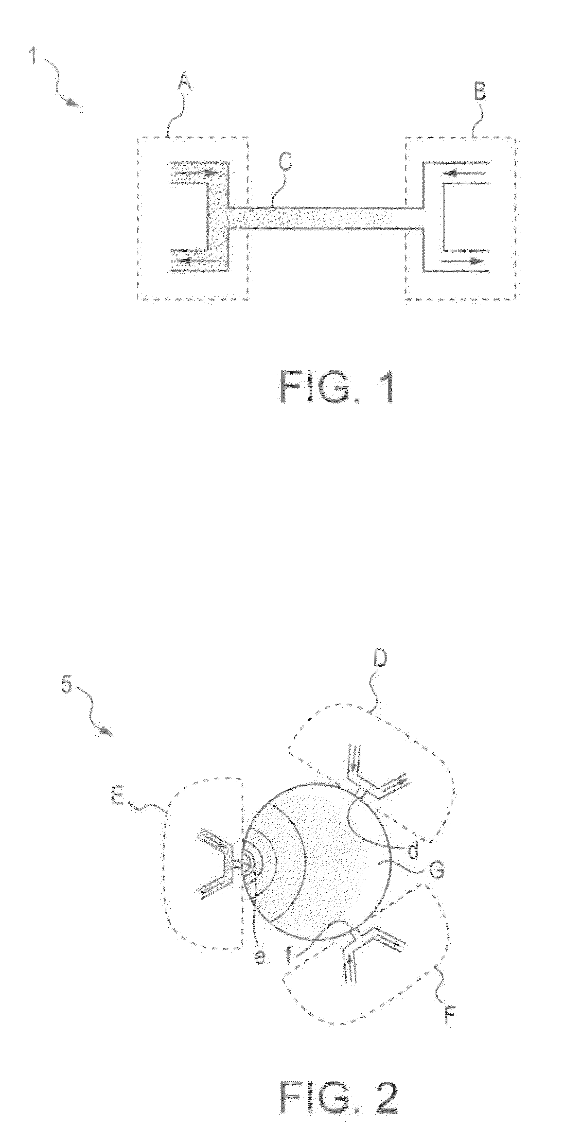
[0054]FIG. 1 schematically illustrates a one dimensional design of a cross channel gradient generator. The device 1 generally includes two convection units, designated as A and B, separated by a microchannel C that provides fluid communication between the convection units A and B. A mass balance at each convection unit A, B, or the “T” junction at each end of the microchannel C, demonstrates that matching bulk flow rates through respective inlets and outlets is a necessary condition to decouple convection through each side channel of convection units A, B from diffusion across the main channel C. If the flow at one convection unit carries a solute concentration and flow at the other convection unit carries buffer, a diffusive gradient develops across the microchannel C and remains constant as long as the flows in the convection units A and B remain constant.

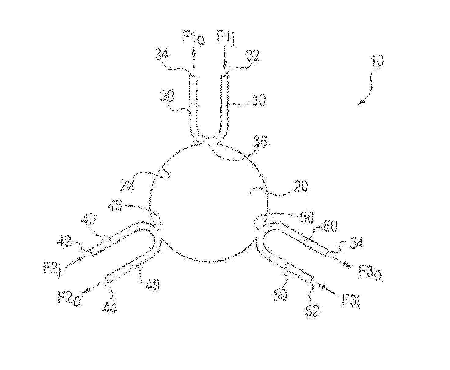
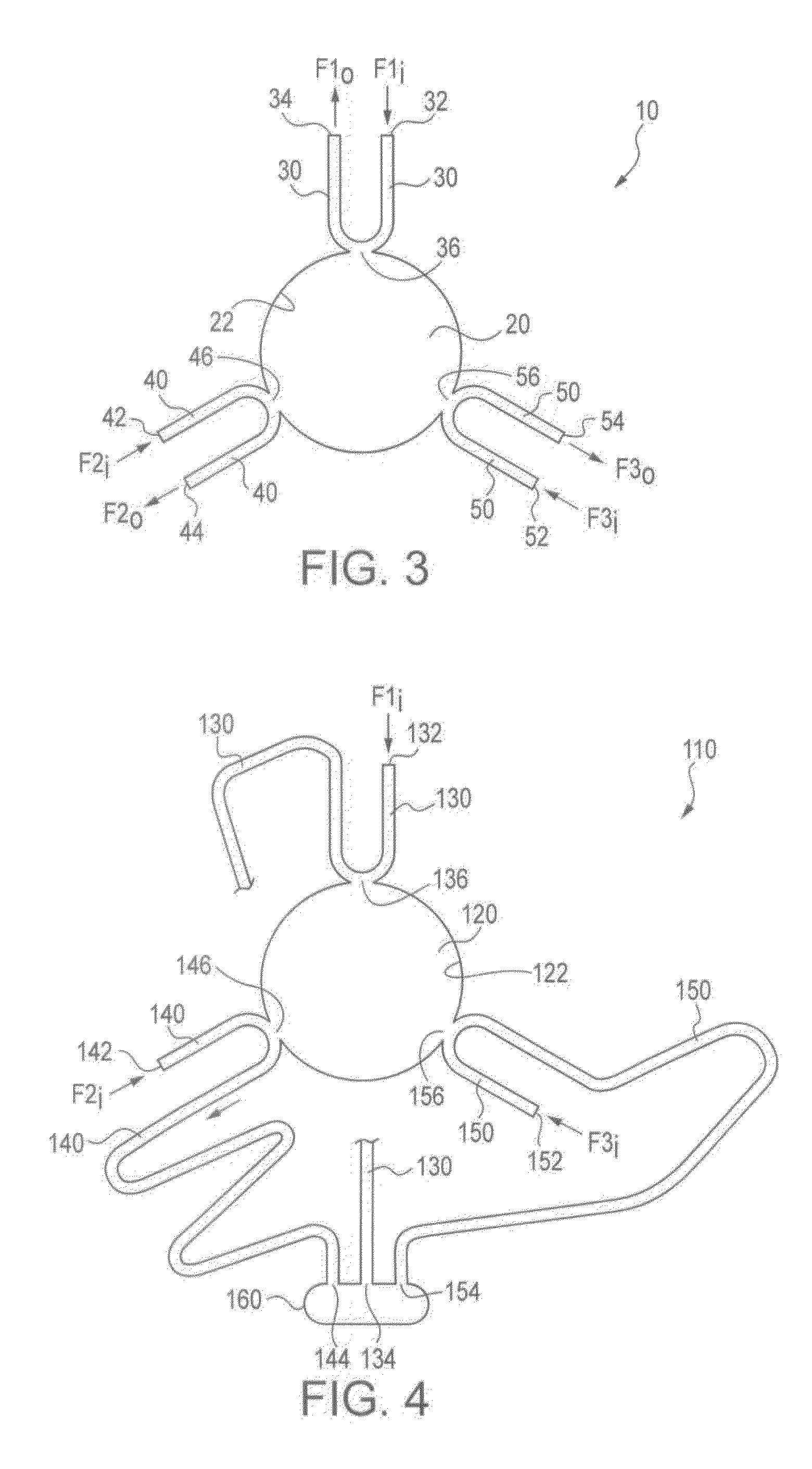
[0055]In accordance with an aspect of the present invention, this concept is extended to a multi di...


PUM

PropertyMeasurementUnit
areasaaaaaaaaaa
thickaaaaaaaaaa
diameteraaaaaaaaaa

Abstract

A microfluidic device is described, capable of generating multiple spatial chemical gradients simultaneously inside a microfluidic chamber. The chemical gradients are generated by diffusion, without convection, and can either be maintained constant over long time periods, or modified dynamically. A representative device is described with a circular chamber in which diffusion occurs, with three access ports for the delivery and removal of solutes. A gradient typically forms in minutes, and can be maintained constant indefinitely. Gradients overlapping with different spatial location, and a controlled rotation of a gradient formed by diffusion are demonstrated. The device can also be used to evaluate chemotactic responses of bacteria or other microorganisms in the absence of convective flow.

Description

CROSS REFERENCES TO RELATED APPLICATIONS[0001]The present application claims priority upon U.S. provisional application Ser. No. 61 / 073,260 filed on Jun. 17, 2008.STATEMENT AS TO RIGHTS TO INVENTION(S) MADE UNDER FEDERALLY-SPONSORED RESEARCH AND DEVELOPMENT[0002]The US Government, through the National Institute of Standards and Testing, is the owner of this invention.FIELD OF INVENTION[0003]The presently disclosed embodiments are directed to the field of microfluidics, methods and applications involving such, and related devices.BACKGROUND OF THE INVENTION[0004]Chemical gradients generated by the release and diffusion of soluble factors mediate many complex processes in biology. A chemical gradient provides not only information about the existence of a particular signal, but also provides spatial information. For example, a motile cell moving through a gradient in a direction of increasing concentration will eventually find the source of the chemical signal. This process, i.e., the ...

Claims


Application Information

Patent Timeline
Patent Type & Authority Patents(United States)
IPC IPC(8): G01N15/06G01N33/00G01N33/48
CPCB01F13/0059B01F13/0093B01F15/0404Y10T436/11B01L3/5027Y10T436/25C12M23/16C12M41/46B01F33/30B01F33/3039B01F35/81
Inventor LOCASCIO, LAURIE E.ATENCIA-FERNANDEZ, FRANCISCO JAVIER
Owner THE UNITED STATES OF AMERICA AS REPRESENTED BY THE SECRETARY OF THE COMMERCE
Why Eureka
Try Eureka