System, method and computer program product for remotely actuating a lock via a cellular communication link

a technology of remote actuation and lock, which is applied in the direction of anti-theft devices, programs, instruments, etc., can solve the problems of unsurprising widespread use of these revolutionary devices, inability to meet the requirements of fcc regulations, and insufficient technology

Inactive Publication Date: 2012-07-10
LERNER MOSES
View PDF4 Cites 5 Cited by
  • Summary
  • Abstract
  • Description
  • Claims
  • Application Information

AI Technical Summary

Benefits of technology

[0013]The cell phone would act as a detector for the lock. Acting as a user interface, user's cell phone allows the user to check whether lock is opened or closed. With the present system, the user may open and close lock without having the inconvenience of carrying heavy bundles of keys. With the present invention, the user will have a versatile mechanism, which is always accessible. No need to fear losing or leaving a key inside a home or car.
[0014]In one embodiment, as an example, use of the present system would be very simple and straightforward. To access menu options of the present invention, the user would input a unique personal identification number (PIN) by pressing the numeric keypad on the cell phone. Once in the menu, the user would simply scroll through the options to select the desired actions. When any of the remote actions are performed with the phone, the controller is tuned to the specific frequency generated by the cellular communication link. Upon reception of the signal generated by the cell phone, the circuitry in the controller would generate an ‘enable’ signal to a logic device, which would apply a voltage level to an actuator of lock. In this manner, the lock can be secured or opened, depending on the desired action.

Problems solved by technology

However, nonexistent technology and stringent FCC regulations postponed availability until 1982, when the FCC authorized commercial cellular use.
Today's widespread use of these revolutionary devices is unsurprising, since they now offer a virtually endless array of benefits.

Method used


Image

  • System, method and computer program product for remotely actuating a lock via a cellular communication link
  • System, method and computer program product for remotely actuating a lock via a cellular communication link
  • System, method and computer program product for remotely actuating a lock via a cellular communication link

Examples


Embodiment Construction

[0036]The present invention will now be described more fully hereinafter with reference to the accompanying drawings, in which a preferred embodiment of the invention is shown. This invention may, however, be embodied in many different forms and should not be construed as limited to the embodiment set forth herein. Rather, this embodiment is provided so that this application will be thorough and complete, and will fully convey the true scope of the invention to those skilled in the art. Like numbers refer to like elements throughout the figures.

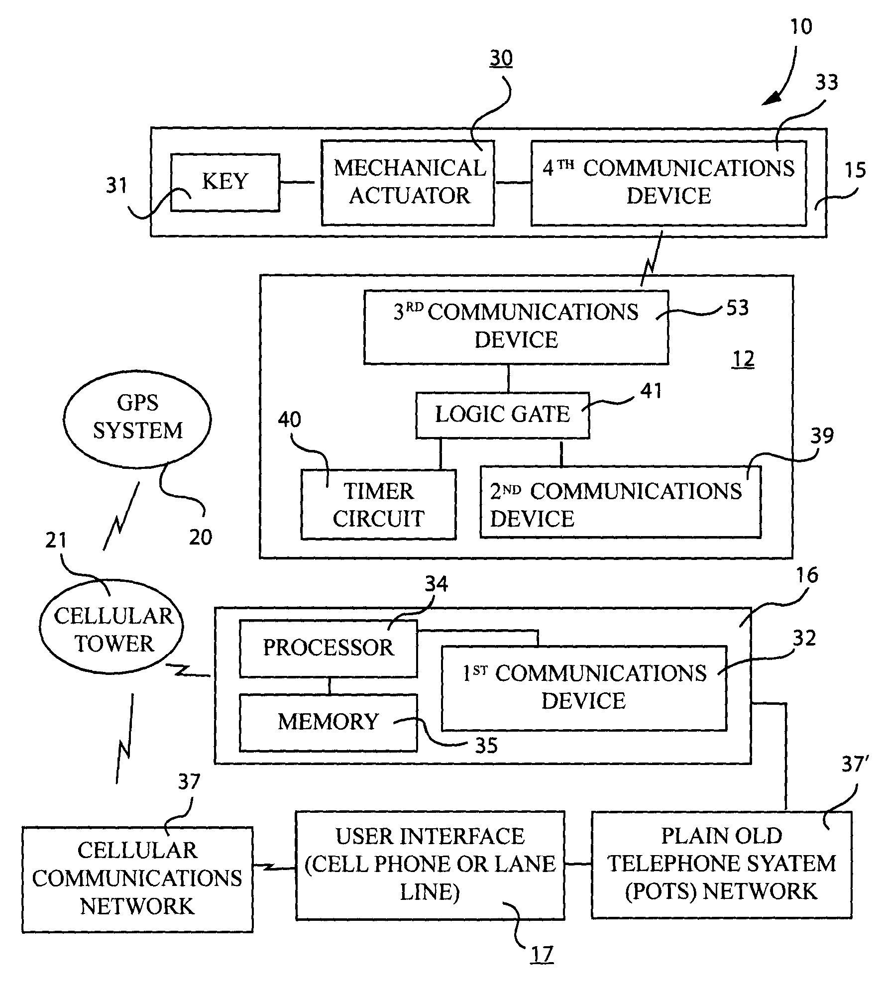
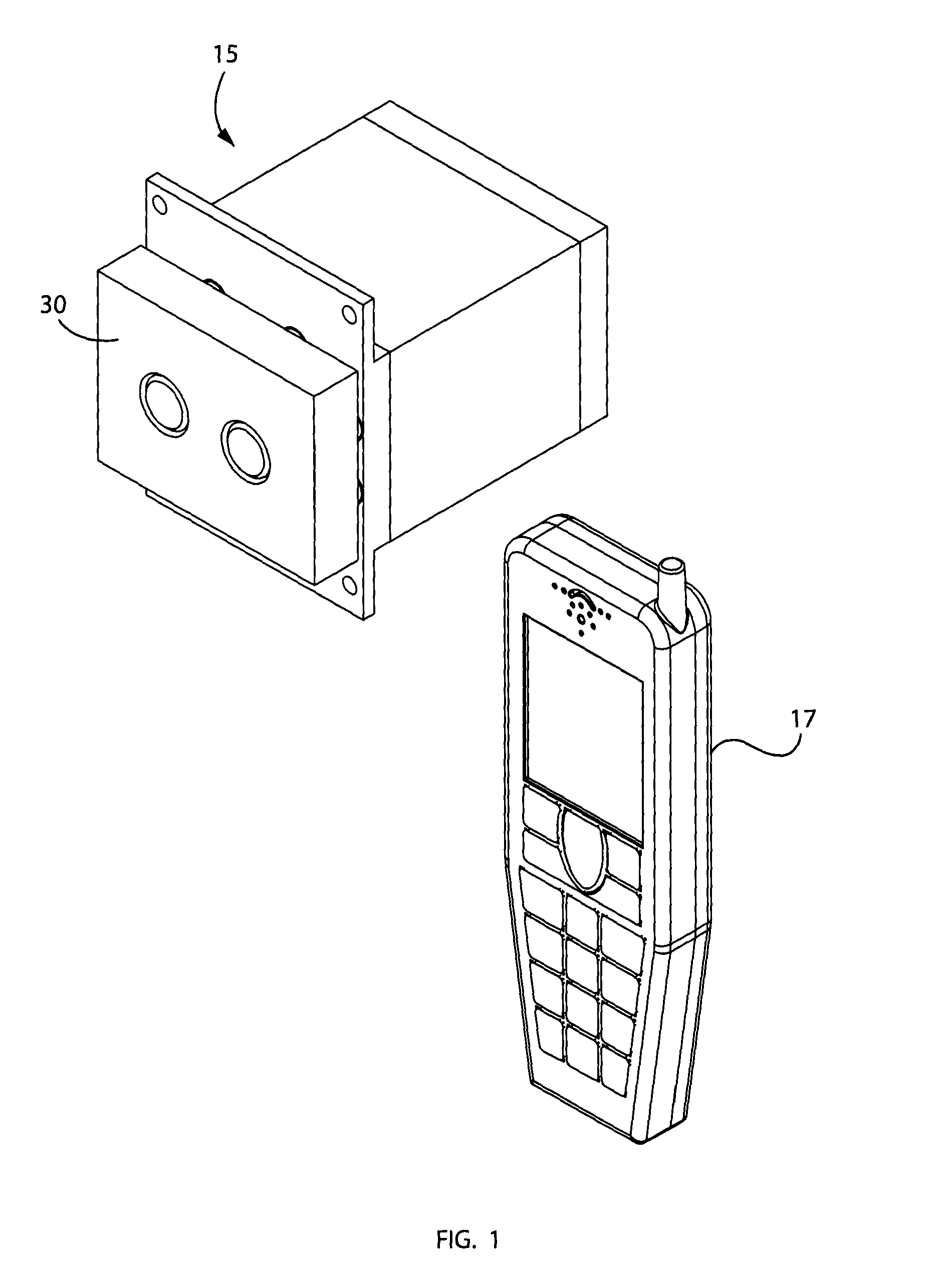
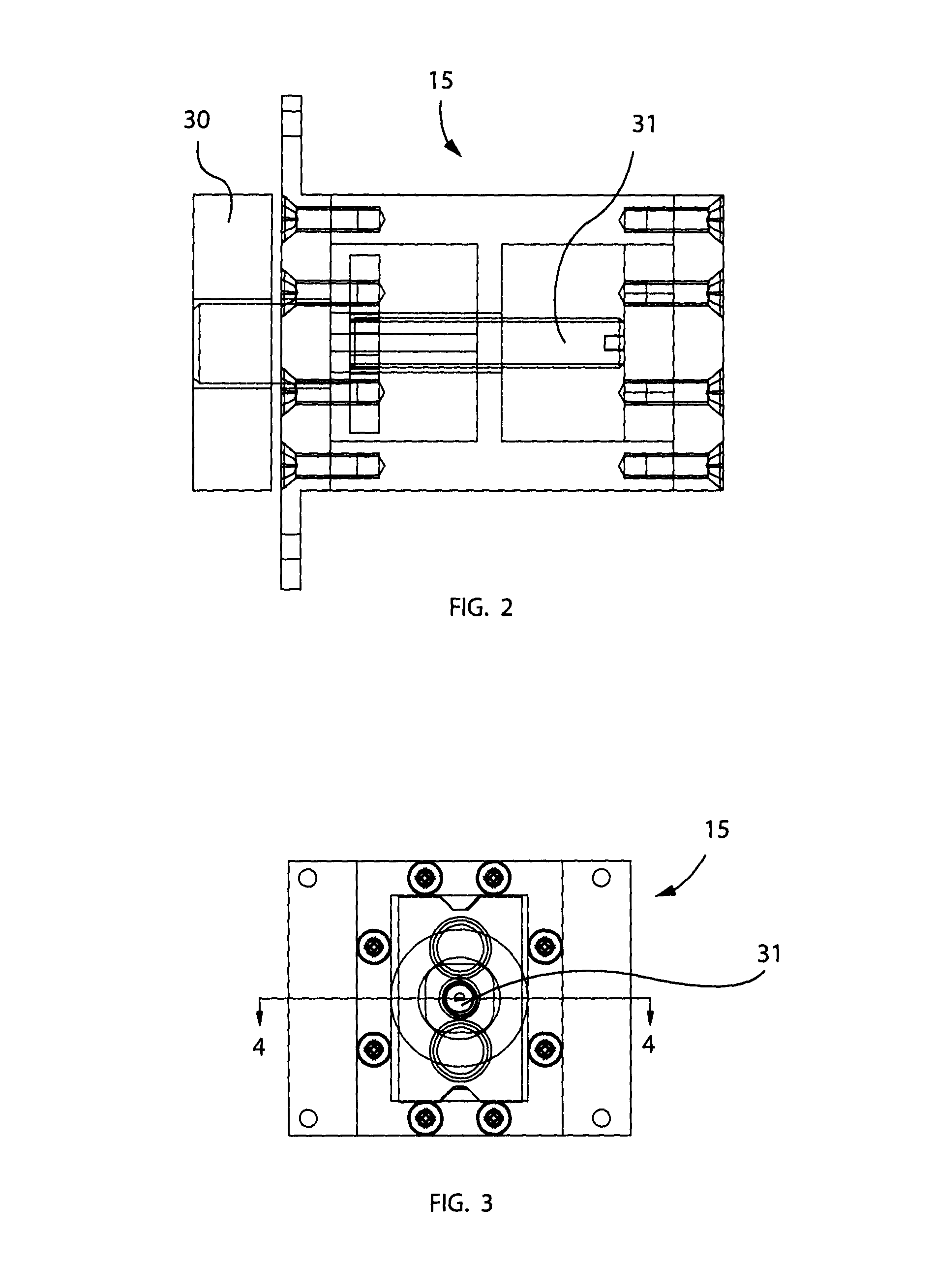
[0037]The present invention is referred to generally in FIGS. 1-5 by the reference numeral 10 and is intended to provide a system, method and computer program product to remotely actuate a lock 15 between alternate operating modes by learning of real-time operating conditions of the lock 15 environment. It should be understood that the present invention 10 may be used to actuate many different types of locks 15 for a variety of operating syst...


PUM


Abstract

A wireless lock actuating system allows user to remotely toggle an existing device between operating and non-operating modes. The system preferably includes a lock and a user interface that generates input signals upon receiving corresponding user inputs respectively. A communications network is communicatively linked to the user interface for transferring the input signals to a remote location, and a service provider is communicatively coupled to the user interface via the communications network. The service provider is responsive to the input signals by generating and transmitting instruction signals and inquiry signals upon receiving corresponding ones of the inputs signals respectively. A controller generates and transmits control signals to the lock upon receiving the instruction signals respectively. Thus, the lock is automatically toggled between locked and unlocked modes upon receiving the control signals from the controller respectively.

Description

CROSS REFERENCE TO RELATED APPLICATIONS[0001]This application claims the benefit of U.S. Provisional Application No. 61 / 065,829, filed Feb. 19, 2008, the entire disclosures of which are incorporated herein by reference.STATEMENT REGARDING FEDERALLY SPONSORED RESEARCH OR DEVELOPMENT[0002]Not Applicable.REFERENCE TO A MICROFICHE APPENDIX[0003]Not Applicable.BACKGROUND OF THE INVENTION[0004]1. Technical Field[0005]This invention relates to remotely actuated lock systems and, more particularly, to a remotely actuated lock system that is accessible via a cellular communications network for allowing a user to toggle a lock via a cell phone.[0006]2. Prior Art[0007]Ever since its first appearance nearly eighty years ago, wireless remote technology has continuously evolved to make many aspects of everyday life more convenient. The first machines to be operated by remote control were used mainly for military purposes. Radio-controlled motorboats, developed by the German navy, were used to ram...

Claims


Application Information

Patent Timeline
Patent Type & Authority Patents(United States)
IPC IPC(8): G05B23/00
CPCG07C9/00103G07C9/00119G07C9/00944G07C9/27G07C9/29
Inventor LERNER, MOSES
Owner LERNER MOSES
Why Eureka
Try Eureka