
Thermally conductive polymer compositions having low thermal expansion characteristics

a polymer composition and thermal expansion technology, applied in the direction of chemistry apparatus and processes, synthetic resin layered products, transportation and packaging, etc., can solve the problems of differential expansion between the substrates, introduction of a great deal of localized mechanical stresses into the assembly, and in the early art, to achieve the effect of imparting thermal conductivity to the polymer matrix, maintaining or enhancing the dielectric properties of the base polymer, and low cte properties

Active Publication Date: 2012-07-17
TICONA POLYMERS INC
View PDF11 Cites 12 Cited by
  • Summary
  • Abstract
  • Description
  • Claims
  • Application Information

AI Technical Summary

Benefits of technology

"The present invention provides an injection moldable, thermally conductive polymer composition with ultra low CTE properties that are suitable for use in high precision electronics assemblies and over molding applications in conjunction with ceramic substrates. The composition exhibits highly desirable material properties including an ultra low CTE and greatly reduced optical anisotropy. The composition is net shape injection moldable and has an ultra low CTE in the range of between 2 ppm / ° C. and 9 ppm / ° C. The composition is suitable for use as an injection moldable substrate material in place of many prior art substrates currently in use. The technical effects of the invention include improved performance characteristics over a broad operational temperature range without the introduction of mechanical stresses produced by large CTE differentials and the net shape moldable aspect of the composition."

Problems solved by technology

Generally, the difficulty in the prior art arises from the fact that such over-molded thermally conductive polymer materials have a CTE value that is substantially different than the CTE of the encapsulated device.
These different CTE values can lead to undesirable mechanical forces or a transfer of stress resulting in the differential expansion between the substrate and the thermally conductive polymer.
These different expansion and contraction rates lead to the introduction of a great deal of localized mechanical stresses being introduced into the assembly.
The difficult found in this process is that laminate construction is basically a two dimensional process that greatly limits the potential geometry of the finished article.
This method however is mostly impractical because molding operations require a flow pattern that results in orienting the fibers along the flow patterns within the mold thereby creating a large CTE anisotropy wherein the finished part has a great differential in CTE properties within itself.
While both of these disclosures are well suited for their particular application, none of the prior art references provide a solution that is suitable for applications wherein a high precision task requires extreme dimensional stability at greatly elevated operational temperature ranges.
As can be appreciated, during any given print operation a large amount of waste heat is produced within the print head array that must be dissipated.
Further, while an example is provided that discloses a print head, the underlying issue impacts any electronic assembly wherein a high degree of dimensional stability is required even at elevated operational temperature ranges.
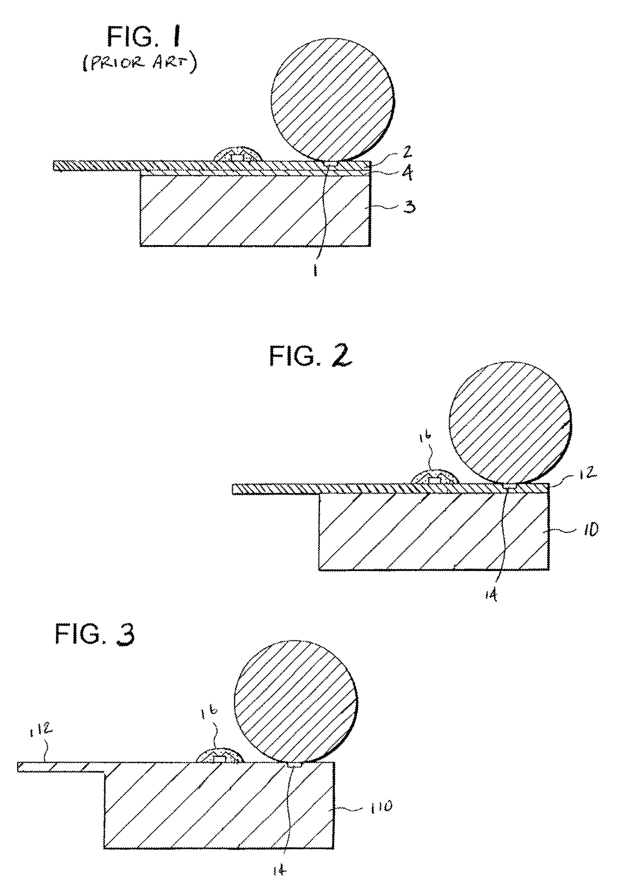
The problem is that machined metallic heat sinks 3 having CTE values that are much greater than the ceramic substrates 2 tend to expand at a higher rate than the substrate to which they are mounted resulting in the introduction of differential stresses in the substrate 2 and frequent failure of the bond 4 between the heat sink 3 and the substrate 2.
Further, metallic heat sinks 3 are relatively expensive to manufacture requiring extensive machining to produce the desired heat sink geometry.
Similarly, the thermally conductive polymers utilized to over mold heat sinks 3 in the prior art exhibit undesirable CTE properties that are also a full order of magnitude greater than the CTE values of the ceramic substrates 2 utilized in such high precision electronics devices.
In addition, as discussed above, where the operation temperature range of the assembly is much lower, a polymer solution works because it succeeds in transferring sufficient heat away from the assembly substrate 2 before the overall device reaches a temperature wherein differential CTE properties become problematic.
In the types of applications anticipated within the present application, it is simply not possible to maintain an operating temperature at such a low threshold.
While forming the substrates and heat sinks from ceramics has produced a high precision and highly thermally conductive assembly, the costs associated with manufacturing such an assembly is dramatically higher than other conventional manufacturing methods.
This type of molding process is time consuming and costly, in addition to the fact that the overall molding process results in a large amount of part shrinkage, wherein further anti-compaction and shrink reduction agents must be added to the base composition to overcome some of the undesirable shrinkage.

Method used


Image

  • Thermally conductive polymer compositions having low thermal expansion characteristics

Examples


example 1

[0033]A composition comprising boron nitride (BN) particles dispersed in a polybutylene terephthalate (PBT) polymer matrix. The BN particles are present in an amount of about 75% by weight based on the weight of the composition and the PBT base polymer matrix comprises the remaining 25% by weight of the composition. The resulting composition has the following properties:

[0034]

CTE (flow)10.2 ppm / ° C.CTE (transverse) 9.6 ppm / ° C.Optical Anisotropy Ratio1.06

example 2

[0035]A composition comprising boron nitride (BN) particles dispersed in a polyphenylene sulfide (PPS) polymer matrix. The BN particles are present in an amount of about 65% by weight based on the weight of the composition and the PPS base polymer matrix comprises the remaining 35% by weight of the composition. This composition had the following properties:

[0036]

CTE (flow)6.8 ppm / ° C.CTE (transverse)6.1 ppm / ° C.Optical Anisotropy Ratio1.1

example 3

[0037]A composition comprising boron nitride (BN) particles dispersed in a liquid crystal polymer (LCP) polymer matrix, wherein the BN particles are present in an amount of about 60% by weight based on the weight of the composition and the LCP base polymer matrix comprises the remaining 40% by weight of the composition. This composition had the following properties:

[0038]

CTE (flow)7.8 ppm / ° C.CTE (transverse)7.3 ppm / ° C.Optical Anisotropy Ratio1.06

[0039]The above examples are meant only to illustrate some compositions that can be made in accordance with the present invention, and these examples should not be construed as limiting the scope of the invention.

[0040]It can therefore be seen that the present invention provides a novel thermally conductive polymer composition that has an ultra low CTE, which makes it particularly suitable for use in conjunction with heat generating electronics assemblies requiring a high degree of dimensional stability. The novel polymer composition can a...


PUM

PropertyMeasurementUnit
densityaaaaaaaaaa
dielectric strengthaaaaaaaaaa
thermally conductiveaaaaaaaaaa

Abstract

An injection moldable, thermally conductive polymer composition that has ultra low CTE properties is provided. The composition is suitable both for substrate applications in high precision electronics assemblies as well as over molding applications in conjunction with ceramic substrates. The composition includes a base polymer matrix material loaded with thermally conductive filler, which imparts thermal conductivity to the polymer matrix while also maintaining or enhancing the dielectric properties of the base polymer. The resultant composition exhibits CTE properties in the range of between 9 ppm / ° C. and 2 ppm / ° C., exhibits an optical anisotropy of below 1.5, and a thermal conductivity of greater than 2 W / m° K. The composition is suitable for use in over molding applications in conjunction with virtually any suitable electronics substrate material without the introduction of mechanical stresses produced by large CTE differentials.

Description

CROSS-REFERENCE TO RELATED APPLICATIONS[0001]This application is related to and claims priority from earlier filed U.S. Provisional Patent Application No. 60 / 576,366, filed Jun. 2, 2004, the contents of which are incorporated herein by reference.BACKGROUND OF THE INVENTION[0002]The present invention relates generally to thermally conductive polymer compositions having very low thermal expansion properties. More specifically, the present invention relates to a thermally conductive polymer composition suitable for use as a substrate in devices that require high dimensional stability, wherein the polymer is characterized as having a coefficient of thermal expansion (CTE) that closely matches the CTE of ceramic materials. The principal benefit to the present invention as compared to the prior art is that the polymer composition can be molded over the heat-generating article so that the composition encapsulates the article. In other instances, the polymer composition, itself, can be mold...

Claims


Application Information

Patent Timeline
Patent Type & Authority Patents(United States)
IPC IPC(8): B32B27/36C08K3/18C08K3/34C08K3/38
CPCC08K3/38C08K2003/382Y10T428/31507Y10T428/31663Y10T428/31725Y10T428/31786
Inventor MILLER, JAMES D.
Owner TICONA POLYMERS INC
Learn More