Directional antenna sectoring system and methodology

a sectoring system and antenna technology, applied in the field of directional antenna sectoring system and methodology, can solve the problems of radio receiver primary source of noise and distortion, radio receiver signal strength change drastically, and may fall below the noise floor, so as to increase the bit rate of each transmission and aggregate capacity of the wireless system, the effect of minimizing interference signals

Inactive Publication Date: 2012-07-17
SITRICK DAVID H ESQ MR
View PDF3 Cites 12 Cited by
  • Summary
  • Abstract
  • Description
  • Claims
  • Application Information

AI Technical Summary

Benefits of technology

[0020]The present invention is not restricted to cellular communication systems—an access point and / or a mobile unit can have multiple directional antennas, each directed to a different sector of three-dimensional space, and the antenna selection is done packet-by-packet. This allows for a packet-by-packet decision and reduces the delay from received signal to transmission and improves the system response time.
[0024]3. Gains are achieved by increasing the range (distance) that a mobile user and an access point can communicate by directing the transmission power to a single sector. By directing the transmission energy in a single direction, it is possible to reduce the interference between different devices and support an increased number of mobile users that can be served by a single access point.
[0025]4. The energy required for effective communication is reduced and will decrease the battery drainage from a mobile user device, thus extending the amount of time between battery charges when users are closer to the access point.
[0026]5. The design allows a device to simultaneously communicate with several access points—increasing the transfer rate from and to the mobile device. Additionally, a mobile device serves as a relay node between access points and mobile devices, and between mobile-to-mobile devices.
[0029]Methods and systems for packet-by-packet directional mobile wireless transmission utilizing plurality of directional antenna sectors are claimed, such that the transmission of each packet is performed by at least one selected antenna sector. The direction of transmission is selected responsive to the direction from which the best electromagnetic signal reception was received. For each plurality of data packets, the transmission direction is selected again. Switching logic couples the out-going transmission signal to selected ones from the plurality of the antennas responsive to the motion of the mobile user. The antenna design in this invention is aimed at increasing the gain and minimizing the interfering signals with respect to large numbers of mobile users who are concurrently and continuously tracking and communicating with their access points, and consequently, increasing the bit rate of each transmission and the aggregate capacity of the wireless system.

Problems solved by technology

A primary source of noise and distortion in radio receivers is derived from multi-path interference.
Because of the superposition of several signals (e.g., echoes and direct waves), the signal strength of the received signal changes drastically and may fall below the noise floor.

Method used


Image

  • Directional antenna sectoring system and methodology
  • Directional antenna sectoring system and methodology
  • Directional antenna sectoring system and methodology

Examples


Embodiment Construction

[0061]While this invention is susceptible of embodiment in many different forms, there are shown in the drawings, and will be described herein in detail, specific embodiments thereof with the understanding that the present disclosure is to be considered an exemplification of the principles of the invention and is not intended to limit the invention to the specific embodiments illustrated.

[0062]The present invention relates to a method and system for increasing transmission capacity of wireless networks.

[0063]General Description

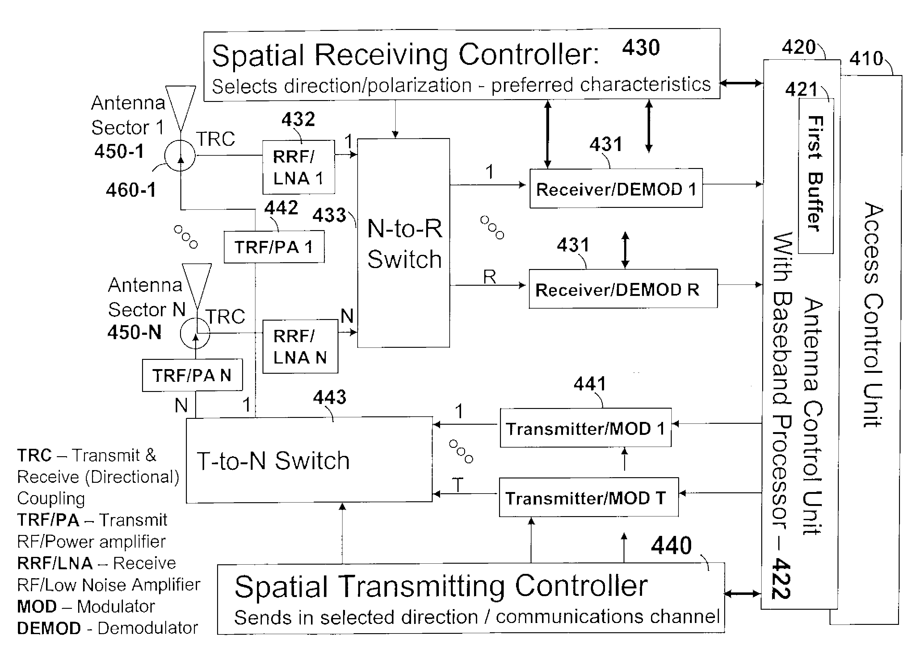
[0064]The following are some acronyms used in this preferred embodiment description:[0065]TRC—Transmit / Receive (Directional) Coupling[0066]TRF / PA—Transmit RF (Radio Frequency) / Power Amplifier[0067]RRF / LNA—Receive RF (Radio Frequency) / Low Noise Amplifier[0068]MOD—Modulator[0069]DEMOD—Demodulator[0070]WL—wireless

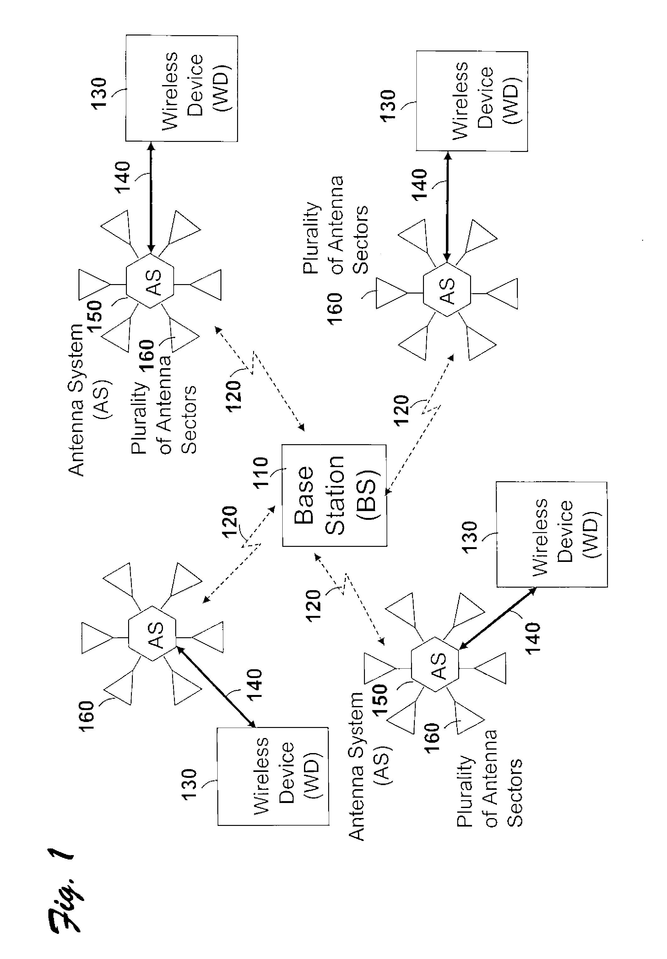
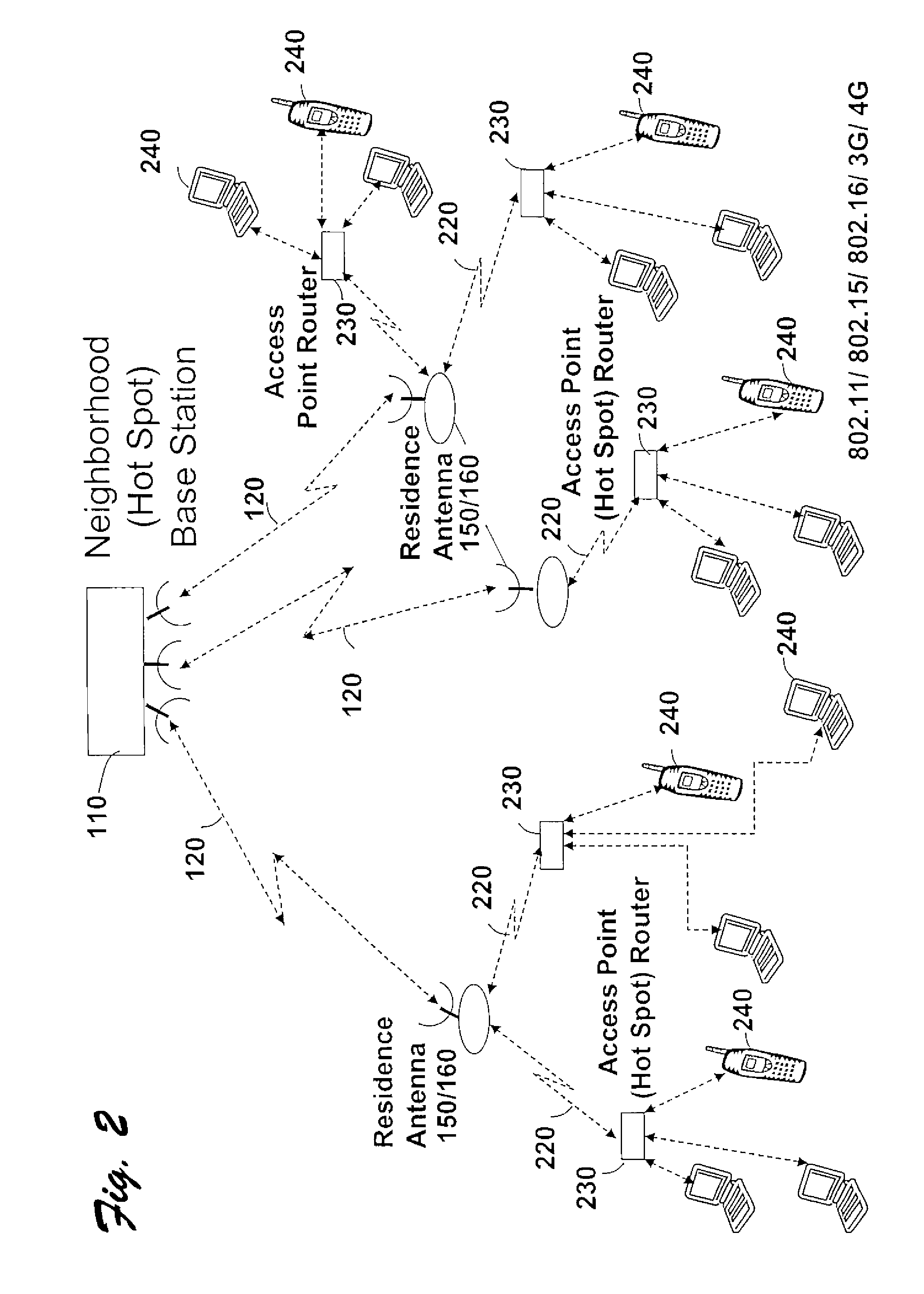
[0071]FIG. 1 and FIG. 2 are general descriptions of the present invention. As shown in FIG. 1, the base station (BS) 110 communicates by means of wirele...


PUM


Abstract

Methods and systems for packet-by-packet directional mobile wireless transmission utilizing plurality of directional antenna sectors, such that, the transmission of each packet is performed by at least one selected antenna sector. A plurality of directional antenna sectors, at least one receiving controller, and at least one transmitting controller, are all physically located at the same location. The direction of transmission is selected responsive to the direction in which the best electromagnetic signal reception was received. For each plurality of data packets, the transmission direction is selected again. Switching logic is coupling the out going transmission signal to selected ones from the plurality of the antennas responsive to the motion of the mobile user. The antenna design in this invention is aimed at increasing the gain and minimizing the interfering signals with respect large number of mobile users who are concurrently and continuously tracking and communicating with their access points, and consequently, increasing the bit rate of each transmission and the aggregate capacity of the wireless system.

Description

RELATED APPLICATIONS[0001]This application is a continuation of and claims priority from U.S. patent application Ser. No. 10 / 814,731; filed: Mar. 31, 2004, claiming priority from Provisional Application Ser. No. 60 / 461,003; filed: Apr. 7, 2003, and claiming priority from Provisional Application Ser. No. 60 / 535,001; filed: Jan. 7, 2004.FEDERALLY SPONSORED RESEARCH OR DEVELOPMENT[0002]Not Applicable.BACKGROUND OF THE INVENTION[0003]Mobile and wireless communications are exhibiting explosive growth—evident by the continued growth of cellular systems, 802.11-based data communications and the increased demand for broadband-based communications. The Internet's success results from IP architecture's robustness, flexibility, and ability to scale over multiple wired networks. The Internet is in the process of expanding to wireless and ad-hoc networking environments. Wireless environments will be able to support mobility—a feature that is desired by the highly dynamic user community. One of t...

Claims


Application Information

Patent Timeline
Patent Type & Authority Patents(United States)
IPC IPC(8): H04B15/00H04B17/00H04B1/38H01Q1/24H01Q21/06H04B7/04
CPCH01Q1/246H01Q21/065H04B7/0491
Inventor OFEK, YORAMGAVISH, BEZALEL
Owner SITRICK DAVID H ESQ MR
Why Eureka
Try Eureka