Reducing pulse narrowing in the transmitter signal that drives a limiting E/O converter for optical fiber channels

a technology of optical fiber channel and limiting e/o converter, which is applied in the direction of electromagnetic transmission, transmission, electrical apparatus, etc., can solve the problems that the transmitter (or modules or components within the transmitter, particularly those that contain a portion of the pre-converter electrical channel), may fail the test, etc., to reduce the effect of pulse width shrinkage, reduce the effect of pulse narrowing and/or minimizing the

Active Publication Date: 2012-07-24
MARVELL ASIA PTE LTD
View PDF12 Cites 13 Cited by
  • Summary
  • Abstract
  • Description
  • Claims
  • Application Information

AI Technical Summary

Benefits of technology

[0010]In one aspect of the invention, an optical transmitter is designed to transmit data over an optical fiber at a specified data rate using on-off keying. The transmitter includes a pre-converter dispersive electrical channel and a limiting E/O converter. The pre-converter electrical channel produces a pre-converter signal that drives the limiting E/O converter. The pre-converter electrical channel is designed to reduce and/or minimize pulse narrowing. For example, the pre-converter electrical channel may be designed to reduce and/or minimize pulse width shrinkage.
[0011]In another aspect of the invention, the testing of optical transmitters that include a pre-converter electrical channel coupled to a limiting E/O converter is based at least in part on metrics for pulse narrowing. In one approach, a repeating data sequence is applied to the pre-converter electrical channel. A pulse narrowing metric of the

Problems solved by technology

For example, the transmitter (or modules or components within the transmitter, particularly those that contain a portion of

Method used


Image

  • Reducing pulse narrowing in the transmitter signal that drives a limiting E/O converter for optical fiber channels
  • Reducing pulse narrowing in the transmitter signal that drives a limiting E/O converter for optical fiber channels
  • Reducing pulse narrowing in the transmitter signal that drives a limiting E/O converter for optical fiber channels

Examples


Embodiment Construction

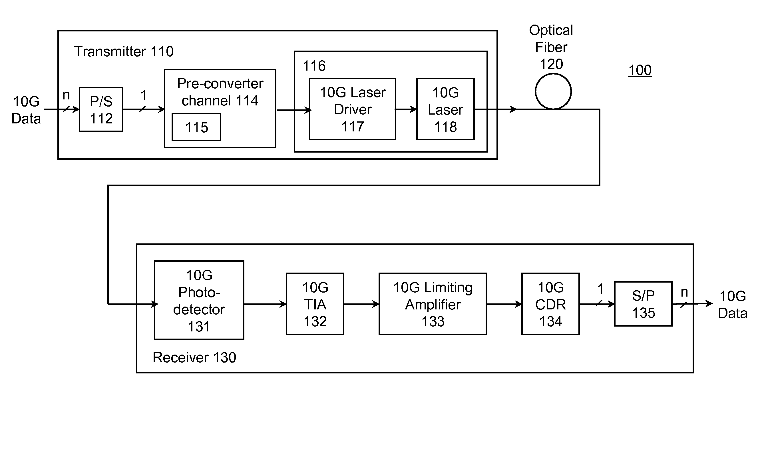
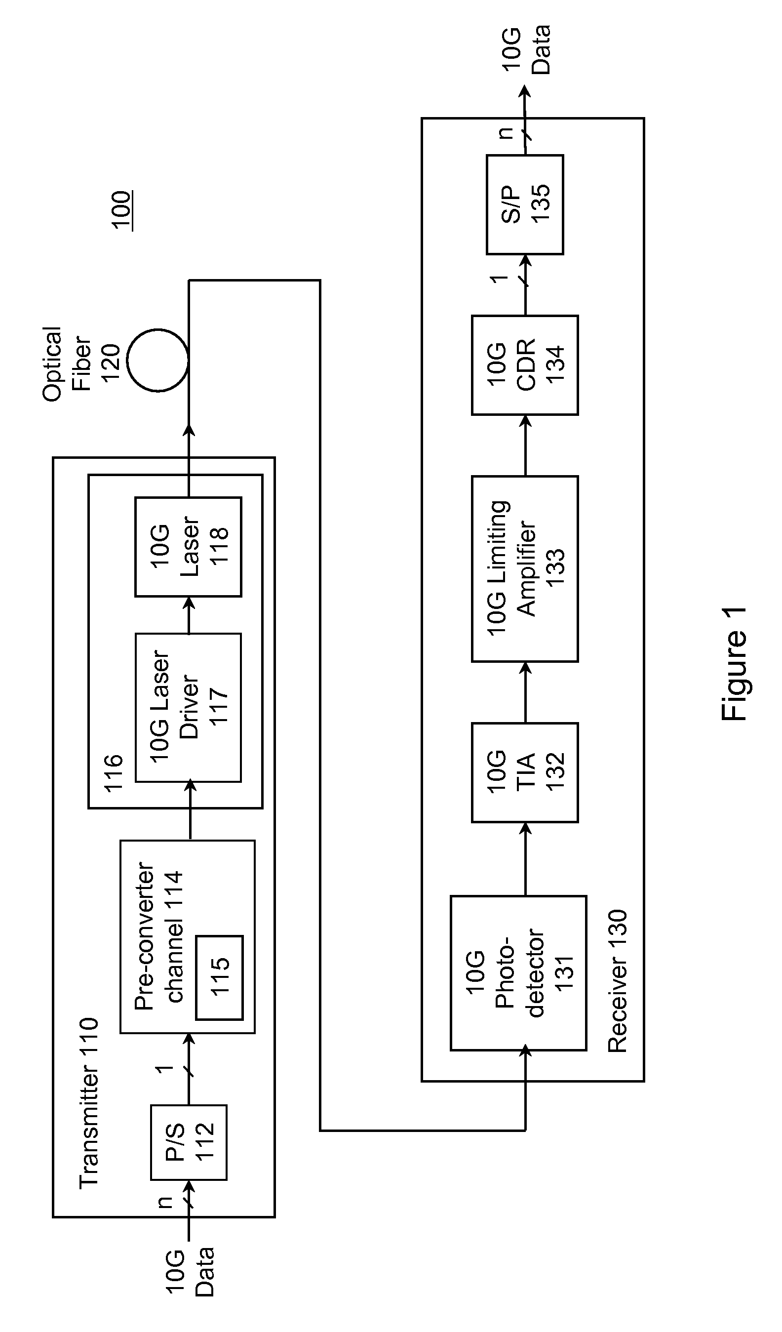
[0026]FIG. 1 is a block diagram of a 10G optical fiber communications link 100 according to the present invention. The link 100 includes a transmitter 110 coupled through optical fiber 120 (the channel) to a receiver 130. A typical transmitter 110 may include a serializer, or parallel / serial converter (P / S), 112 for receiving 10G data from a data source on a plurality of parallel lines and providing serial data to rest of the transmitter. The limiting E / O converter 116 limits the received electrical signal and converts it to an optical form suitable for transmission over fiber 120. The term “pre-converter electrical channel”114 will be used to refer to components between the data input and the limiting E / O converter 116. The pre-converter electrical channel 114 conditions the signal input to the limiting E / O converter 116. For convenience, this signal will be referred to as the pre-converter signal.

[0027]In the specific example of FIG. 1, the pre-converter electrical channel 114 inc...


PUM


Abstract

A transmitter reduces or minimizes pulse narrowing. In one approach, an optical transmitter is designed to transmit data over an optical fiber at a specified data rate using on-off keying. The transmitter includes a pre-converter electrical channel and a limiting E/O converter. The pre-converter electrical channel produces a pre-converter signal that drives the limiting E/O converter. The pre-converter electrical channel is designed to reduce pulse narrowing in the pre-converter signal. In one implementation, the pre-converter electrical channel includes a pre-emphasis filter that is designed to minimize pulse width shrinkage.

Description

CROSS-REFERENCE TO RELATED APPLICATION(S)[0001]This application claims priority under 35 U.S.C. §119(e) to U.S. Provisional Patent Application Ser. No. 60 / 836,295, “Improvement of Rx / EQ SNR by Overcompensation of the Tx Electrical Channel,” filed Aug. 7, 2006. The subject matter of all of the foregoing is incorporated herein by reference in its entirety.BACKGROUND OF THE INVENTION[0002]1. Field of the Invention[0003]This invention relates generally to the transmission of data over optical fibers and, more particularly, to reducing the amount of pulse narrowing in the electrical signal that drives a limiting E / O converter in the transmitter in order to improve the performance of the transmission.[0004]2. Description of the Related Art[0005]Optical fiber is widely used as a communications medium in high speed digital networks, including local area networks (LANs), storage area networks (SANs), and wide area networks (WANs). There has been a trend in optical networking towards ever-inc...

Claims


Application Information

Patent Timeline
IPC IPC(8): H04B10/04
CPCH04B10/58H04B10/524H04B10/504
Inventor LINDSAY, THOMAS A.
Owner MARVELL ASIA PTE LTD
Why Eureka
Try Eureka