
Method and apparatus for assembling a complex product in a parallel process system

a technology of parallel process and assembly line, applied in the direction of total factory control, programme control, electric controller, etc., can solve the problems of inefficiency of assembly lines, inability to utilize assembly lines to manufacture any component of automobiles, and inability to use particular assembly lines without major retooling

Active Publication Date: 2012-07-24
COMAU LLC
View PDF44 Cites 24 Cited by
  • Summary
  • Abstract
  • Description
  • Claims
  • Application Information

AI Technical Summary

Benefits of technology

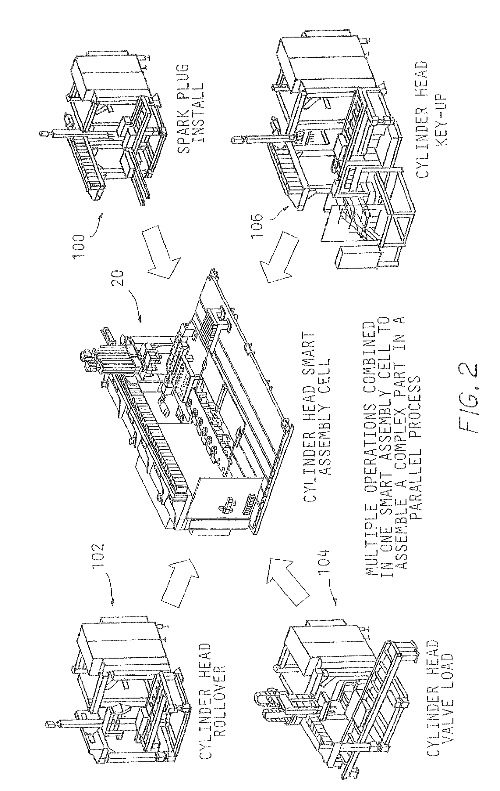
The present invention provides a method and apparatus for assembling a complex product in a parallel process system. The method involves providing a collection of subcomponents and a base component to a loading station, where they are automatically assembled using a computerized assembly cell. The complex product is then automatically transported to a computerized test cell for testing its functionality. The test cell also has a rollover fixture for securing and rotating the complex product in a desired orientation for testing. The apparatus includes a loading station, a plurality of computerized assembly cells, a computerized test cell, and a delivery station. The transport system may include a computerized overhead gantry system or a computerized robotic arm for automatically picking and placing the kit container and the base component. The computerized assembly cells and the computerized test cell may also have a rollover fixture for securing and rotating the components during assembly and testing.

Problems solved by technology

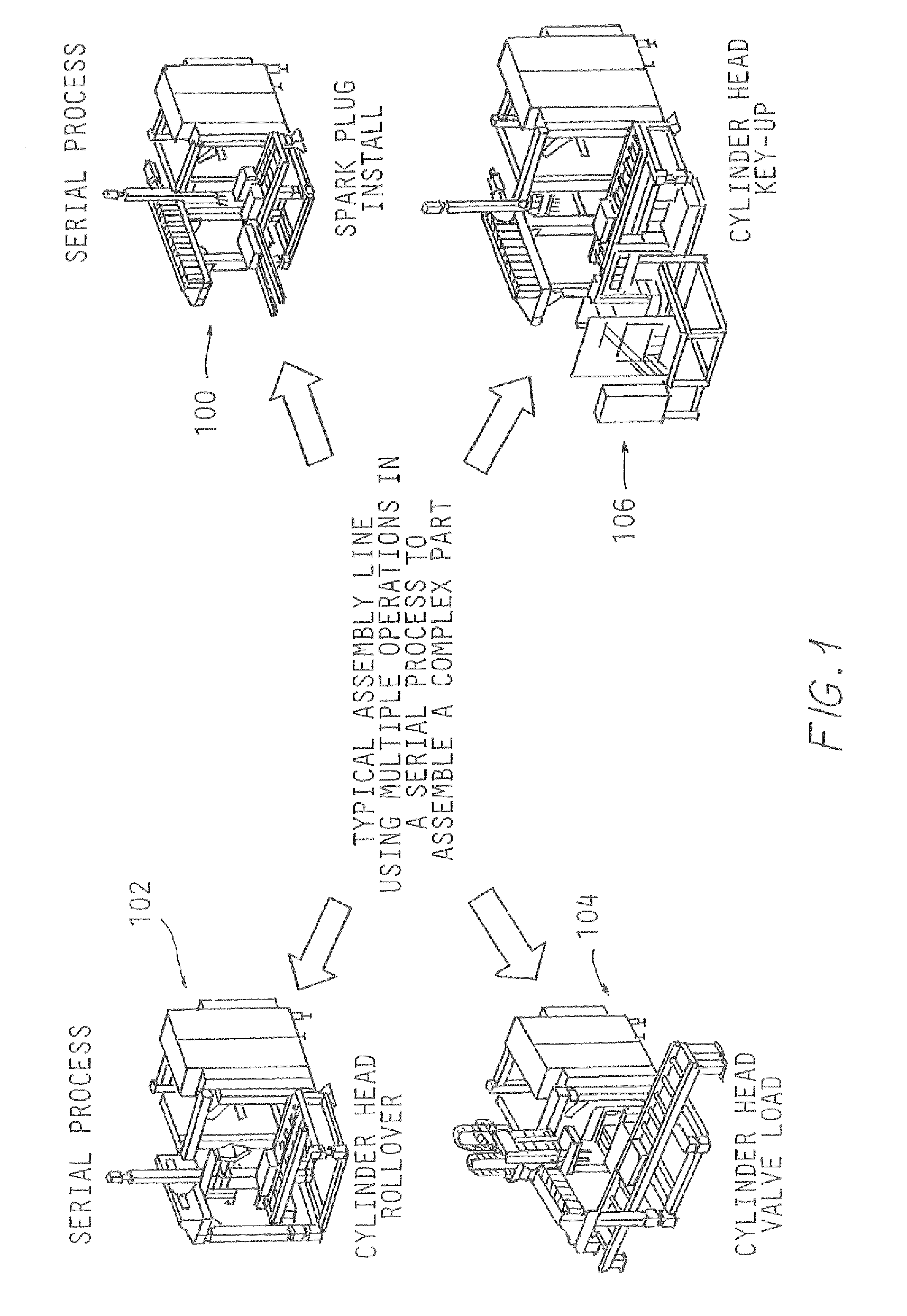
Serial process systems are even more common when such products are complex in nature, thereby requiring the assembly of a variety of different subcomponents and various individual components in various locations on the product.
Although assembly lines have been utilized throughout the history of the manufacturing industry, such assembly lines are plagued with inefficiencies.
Thus, such assembly lines cannot be utilized to manufacture any component of an automobile, but rather, they can be only utilized to build certain specific components.
Therefore, if the particular component is no longer needed, for instance, if the particular model of automobile in which the component is utilized is no longer being manufactured, then the particular assembly line cannot be utilized without major retooling.
This is, of course, a very timely and costly task and one that is undesirable in an industrial environment.
If a problem occurs at that particular workstation such that the task can no longer be performed, for instance, a tool breaks, the transport system shuts down, certain components are defective, etc., then the entire assembly line may have to be shut down until the problem is corrected.
When this occurs, manufacturing of the particular product is halted, thereby causing a shortage of the product being manufactured or assembled on that particular assembly line.
Such a shortage of products could create shortages in other assembly lines thereby requiring other assembly lines to shut down.
Such uncertainty in the operation of the assembly line may lead to a shortage or a surplus of components.
A shortage of components may lead to other assembly lines being short of parts, and a surplus of components may mean that unnecessary parts have been produced, thereby wasting time and money.
Either situation creates an inefficiency that is undesirable in an industrial environment.
The floor space in a manufacturing facility can be rather expensive, and therefore, it is always desirable to reduce the amount of floor space to produce a particular product.

Method used


Image

  • Method and apparatus for assembling a complex product in a parallel process system
  • Method and apparatus for assembling a complex product in a parallel process system
  • Method and apparatus for assembling a complex product in a parallel process system

Examples


Embodiment Construction

[0046]Referring to the drawings, the present invention will now be described in detail with reference to the disclosed embodiments.

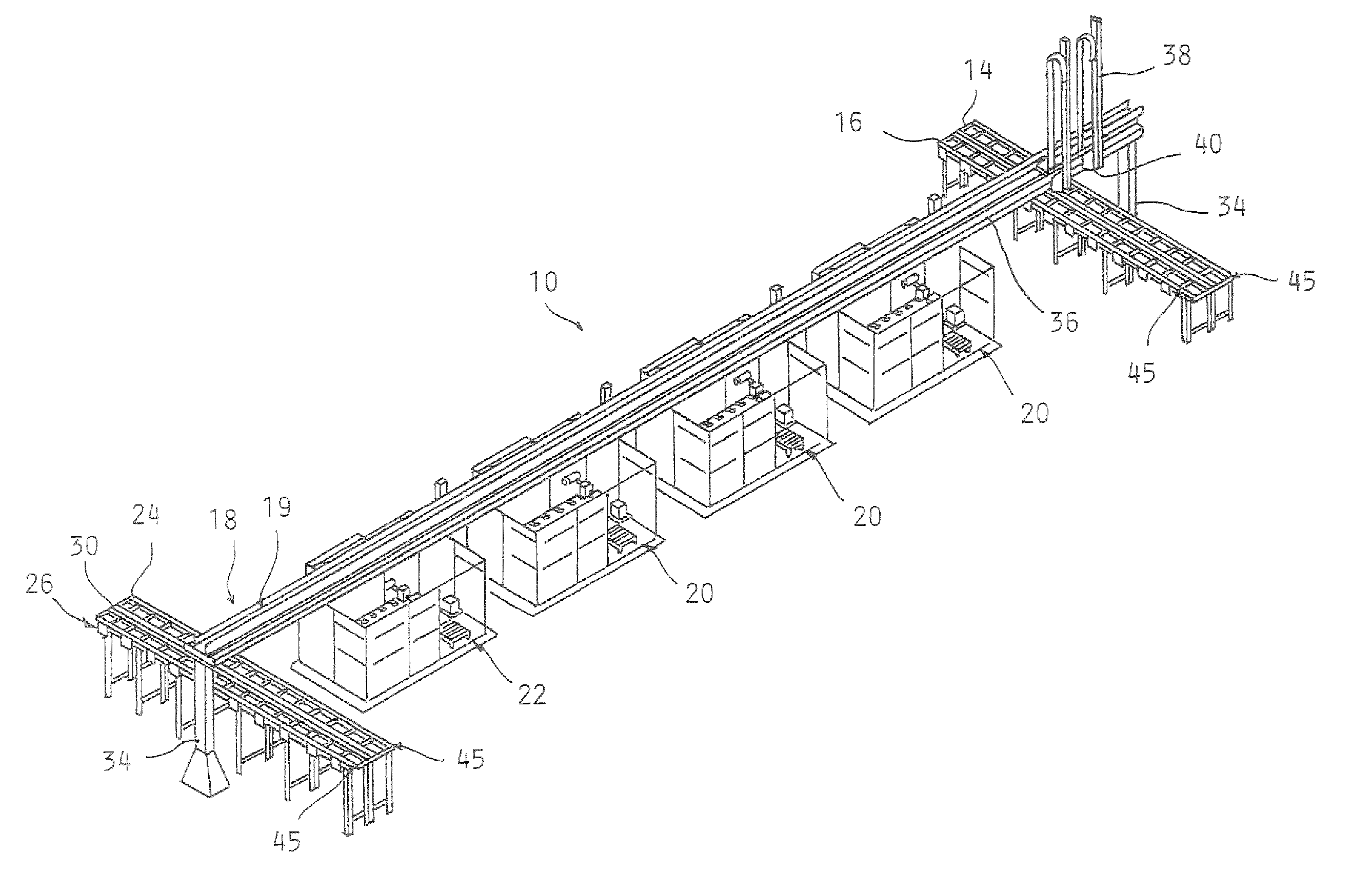
[0047]FIGS. 3-14 illustrate a method and apparatus 10 for assembling a complex product 12 in a parallel process system of the present invention. The method and apparatus 10 for assembling the complex product 12 provides a loading station 13 having a part delivery system 14 and a kit delivery system 16 that deliver the necessary components to the apparatus 10 of the present invention. A transport system 18, which may include, but is not limited to, an overhead gantry or a robot system, extends over the length of the apparatus 10 and independently picks and carries the components from the part delivery system 14 and kit delivery system 16 of the loading station 13 to one of a plurality of similar, computerized assembly cells or workstations 20. In the alternative, the loading and unloading of the components into the assembly cells 20 may be done manually. ...


PUM


Abstract

A method and apparatus for assembling a complex product in a parallel process system wherein a collection of components are provided for assembling the complex product. The present invention involves transferring the collection of the components to one of a plurality of similar computerized assembly cells through the use of a transport system. The collection of components is automatically assembled into the complex product through the use of the computerized assembly cells. The complex product is then transferred from one of the assembly cells to a computerized test cell, where the complex product is tested to ensure for the proper dimensioning and functioning of the complex product. The complex product is then transferred from the test cell via the transport system to either a part reject area or conveyor, if the complex product is defective, or to an automatic dunnage load or part return system, if the complex product is not defective.

Description

CROSS-REFERENCE TO RELATED APPLICATIONS[0001]The subject application claims the priority of U.S. Provisional Patent Application Ser. No. 61 / 007,307, filed on Dec. 12, 2007.FIELD OF THE INVENTION[0002]The present invention relates to methods and apparatuses for assembling complex products and, in particular, a method and apparatus for assembling manufacturing products that utilize flexible and programmable assembly and test cells to enhance the quality and efficiency of assembling a complex product in a parallel process system.BACKGROUND OF THE INVENTION[0003]In today's manufacturing industry, the customary manner of assembling products is with an assembly line in a serial process system. A serial process system is defined as having the complex product travel through successive, single operations or stations in order to complete the assembly of the complex product. Serial process systems are even more common when such products are complex in nature, thereby requiring the assembly of ...

Claims


Application Information

Patent Timeline
Patent Type & Authority Patents(United States)
IPC IPC(8): G05B11/01G06F7/00G06F19/00
CPCB23P19/001B23P19/042B23P21/00B23P21/002G05B19/418G05B19/41805B23P23/04B23P2700/50G05B2219/31054B62D65/10B62D65/00Y02P90/02
Inventor WALLACE, RICHARD A.GRAHAM, JOHNBROWN, THEODORE ROBERT
Owner COMAU LLC
Learn More