Interface circuit and video apparatus
a video apparatus and interface circuit technology, applied in the field of interface circuits and video apparatuses, can solve the problems of inability to realize real time, inability to realize clocks, and inability to process software at the same time, so as to improve signal transmission quality
- Summary
- Abstract
- Description
- Claims
- Application Information
AI Technical Summary
Benefits of technology
Problems solved by technology
Method used
Image

Examples
first embodiment
1. First Embodiment
[Configuration Example of AV System]
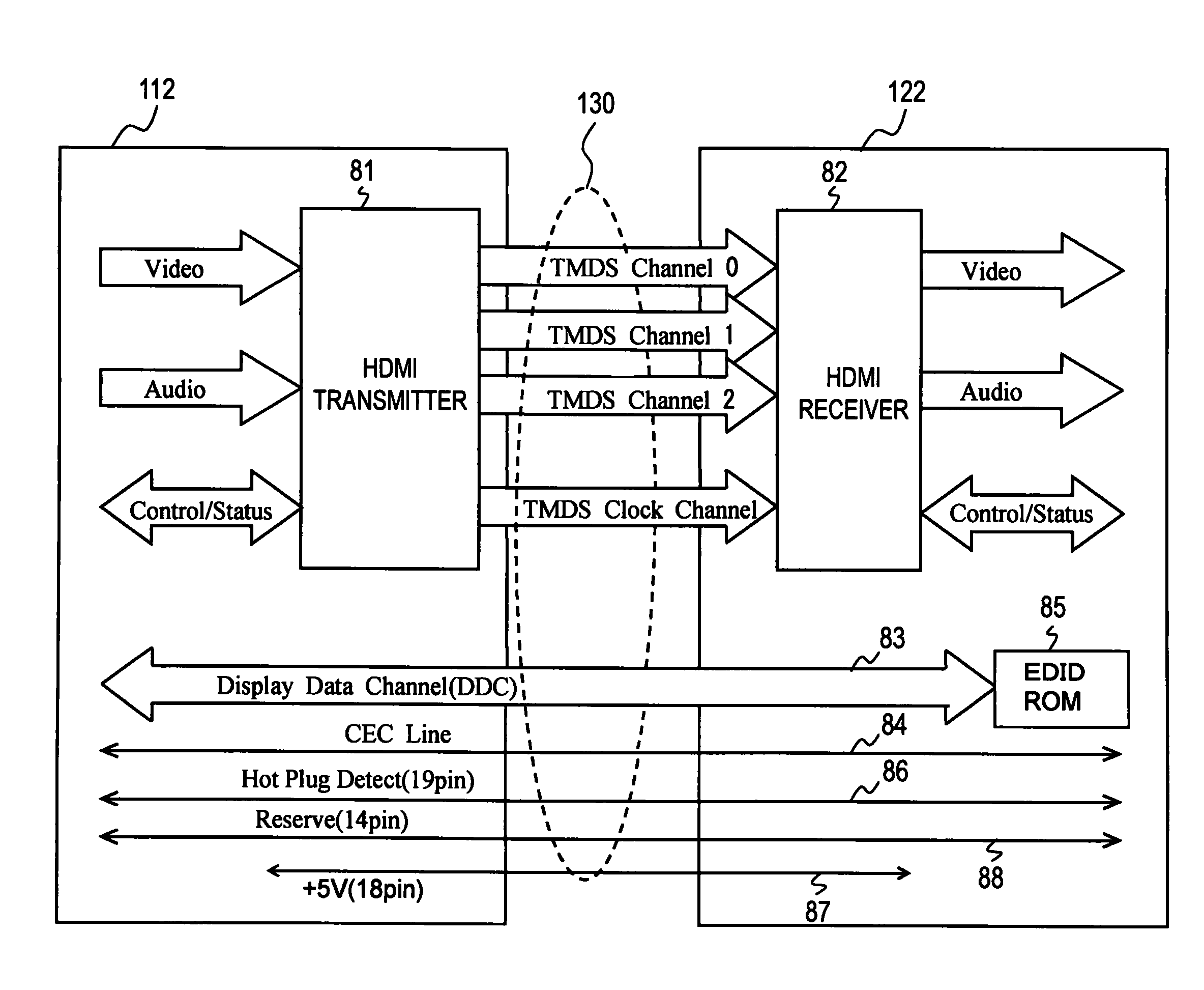
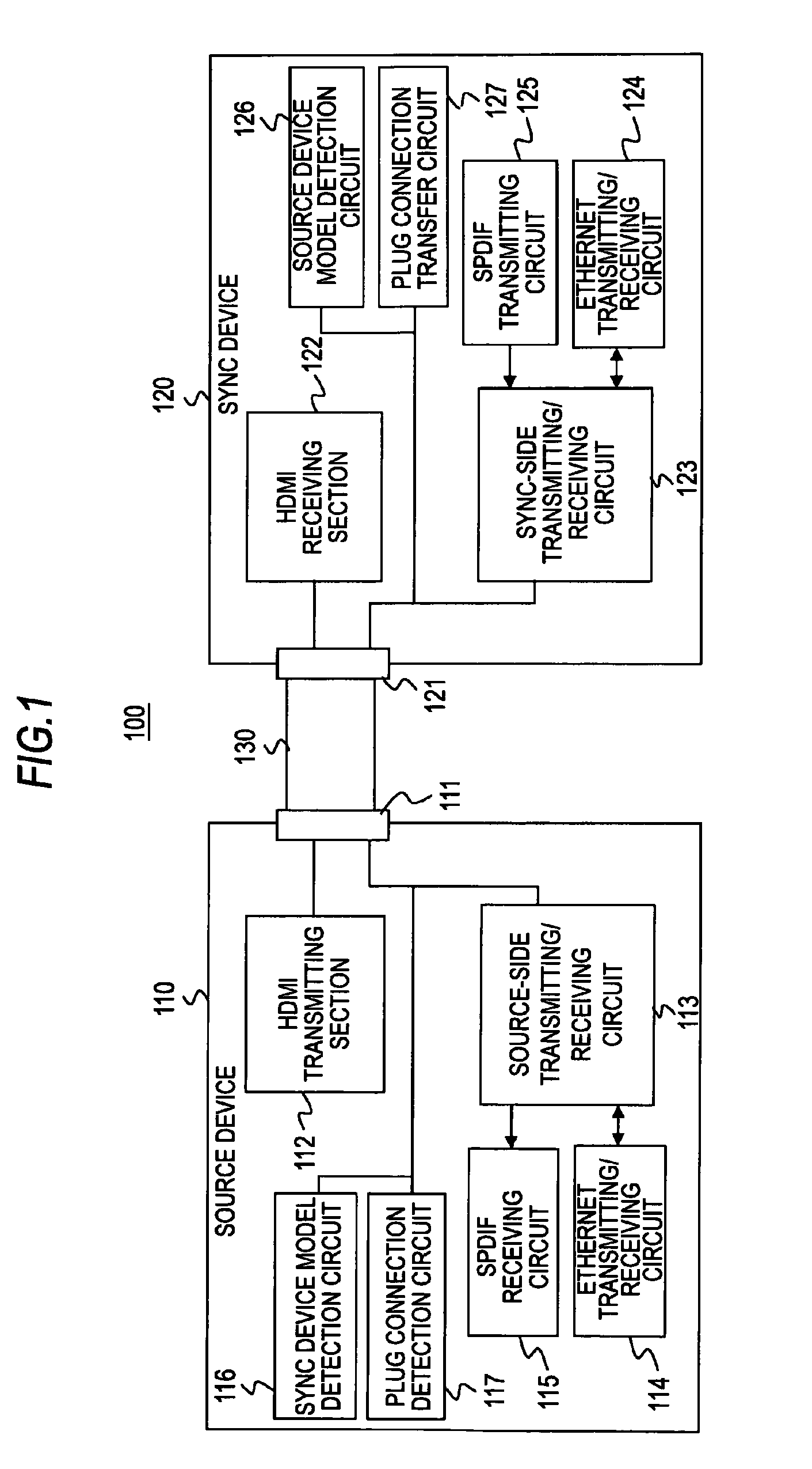
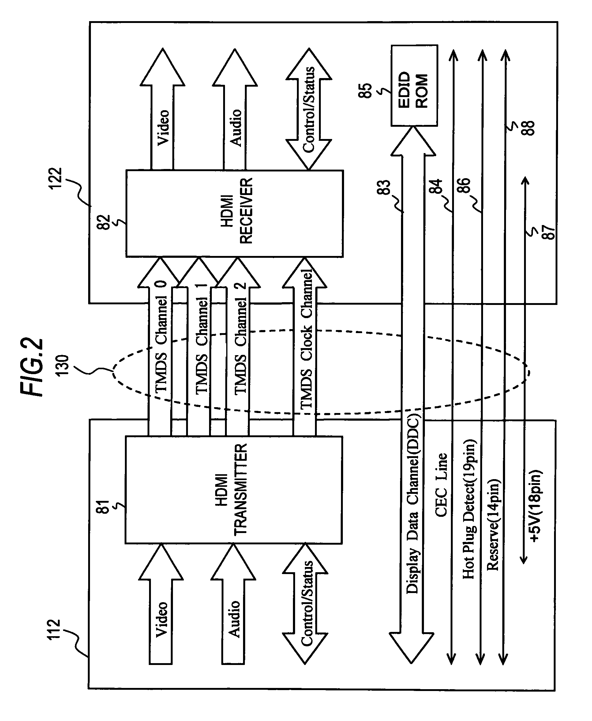
[0070]FIG. 1 shows a configuration example of an AV system 100 according to an embodiment. The AV system 100 has a source device 110, such as a disk recorder or the like, and a sync device 120, such as a television receiver or the like. In the AV system 100, the source device 110 and the sync device 120 are eHDMI-compatible devices. Note that an eHDMI-compatible device means that a communication section is provided which performs communication using a communication path of a reserve line and an HPD line constituting an HDMI cable.
[0071]The source device 110 and the sync device 120 are connected to each other through an HDMI cable 130. That is, the source device 110 has an HDMI terminal 111, and the sync device 120 also has an HDMI terminal 121. One end of the HDMI cable 130 is connected to the HDMI terminal 111 of the source device 110, and the other end of the HDMI cable 130 is connected to the HDMI terminal 121 of the sync dev...
second embodiment
2. Second Embodiment
[0262]An AV system 100A according to a second embodiment has the same configuration as the AV system 100 of FIG. 1 as a whole. In the AV system 100A, a difference from the AV system 100 is a clock system including the SPDIF transmitting circuit 125 of the sync device 120 and the SPDIF receiving circuit 115 of the source device 110.
[Configuration Example of Source-Side Transmitting / Receiving Circuit, Sync-Side Transmitting / Receiving Circuit, and the Like]
[0263]FIG. 23 shows a configuration example of a source-side transmitting / receiving circuit 113, a sync device model detection circuit 116, a plug connection detection circuit 117, and the like of a source device 110 in the AV system 100A. In FIG. 23, corresponding parts in FIG. 12 are represented by the same reference numerals, and detailed descriptions thereof will be omitted.
[0264]In FIG. 23, a difference from FIG. 12 is a clock system including the SPDIF receiving circuit 115. That is, in FIG. 23, instead of t...
third embodiment
3. Third Embodiment
[Configuration Example of AV System]
[0285]FIG. 25 shows a configuration example of an AV system 100B according to an embodiment. The AV system 100B has a source device 110B, such as a disk recorder or the like, and a sync device 120B, such as a television receiver or the like. In the AV system 100B, the source device 110B and the sync device 120B are eHDMI-compatible devices. Note that an eHDMI-compatible device means that a communication section is provided which performs communication using a communication path including a reserve line and an HPD line constituting an HDMI cable.
[0286]The AV system 100 shown in FIG. 1 is configured such that the SPDIF signal can be transmitted from the sync device 120 to the source device 110 in a single direction. In contrast, the AV system 100B shown in FIG. 25 is configured such that the SPDIF signal can be transmitted in two directions between the source device 110B and the sync device 120B. In FIG. 25, corresponding parts in...
PUM
 Abstract
Description
Claims
Application Information
 - R&D
- Intellectual Property
- Life Sciences
- Materials
- Tech Scout
- Unparalleled Data Quality
- Higher Quality Content
- 60% Fewer Hallucinations
Browse by: Latest US Patents, China's latest patents, Technical Efficacy Thesaurus, Application Domain, Technology Topic, Popular Technical Reports.
© 2025 PatSnap. All rights reserved.Legal|Privacy policy|Modern Slavery Act Transparency Statement|Sitemap|About US| Contact US: help@patsnap.com