Cerebrospinal fluid collection tubes and methods

a collection tube and cerebrospinal fluid technology, applied in the field of medical devices, can solve the problems of csf droplets being missed, exacerbated unpredictability of csf drop formation, and procedure can be made more difficult, so as to reduce the risks of spinal tap procedures, increase the predictability of csf collection, and efficient procedure of csf collection

Active Publication Date: 2012-07-31
CREIGHTON UNIVERSITY
View PDF38 Cites 10 Cited by
  • Summary
  • Abstract
  • Description
  • Claims
  • Application Information

AI Technical Summary

Benefits of technology

[0017]Likewise, the bottom end portion may be of any size and / or shape, for example, circular, oval, polygonal, planar, conical, hemispherical or square. The size and / or shape of the bottom end portion facilitates pipetting of the collected CSF or facilitates separation of solids by centrifugation. To facilitate standing the CSF collection tube in an upright position, in cases where the bottom end portion of the CSF collection tube is hemispherical or conical, the tubular sidewall portion can be extended downwardly past the region where the tubular sidewall portion is sealed to the bottom end portion so as to present a substantially planar bottom surface, or rim, that is substantially perpendicular to the tubular sidewall portion.
[0037]Yet another object of the present invention is to reduce the amount of CSF lost or wasted during a spinal tap procedure.

Problems solved by technology

First, because of the difficulty in maintaining the collection tube under the proximal end of the spinal needle and the unpredictable nature of dripping fluids, CSF droplets are sometimes missed, or they run down the outside of the collection tube instead of into the collection tube.
Second, the proximal end of spinal needles typically includes a hub (e.g., a LUER-LOK™ hub). The CSF collects in the hub before forming droplets, and this mass of fluid in the spinal needle hub exacerbates the unpredictability of CSF drop formation and represents a volume of CSF that is not collected.
The procedure can be made more difficult if a patient is unable to remain calm or still, which is common when the patient is very young or very sick.
Increasing the efficiency of CSF collection may reduce the duration of this procedure, which, in turn, may reduce the duration of time that the patient is restrained or given potentially dangerous sedative medications.
The CSF collection procedure also represents significant risk to the patient.
Patients may develop severe side effects from the loss of too much CSF, including severe headaches.
The risk of the patient moving and causing injury exists for the duration of the procedure.
These risks include a risk of lacerating a spinal nerve, lacerating the meninges (causing permanent or persistent leaks of CSF) or bleeding, which complicates the Interpretation of laboratory results.
These risks are increased in very young patients who are more likely to move during the procedure.
Failure to collect adequate amounts of CSF can result in a misdiagnosis or an absence of a definitive diagnosis.
If mistreated, the patient's illness may worsen.
Otherwise, the patient may be subjected to the potentially life threatening side effects of a broad range of treatments.

Method used


Image

  • Cerebrospinal fluid collection tubes and methods
  • Cerebrospinal fluid collection tubes and methods
  • Cerebrospinal fluid collection tubes and methods

Examples


Embodiment Construction

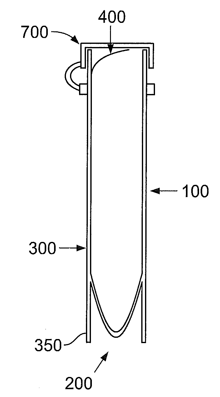
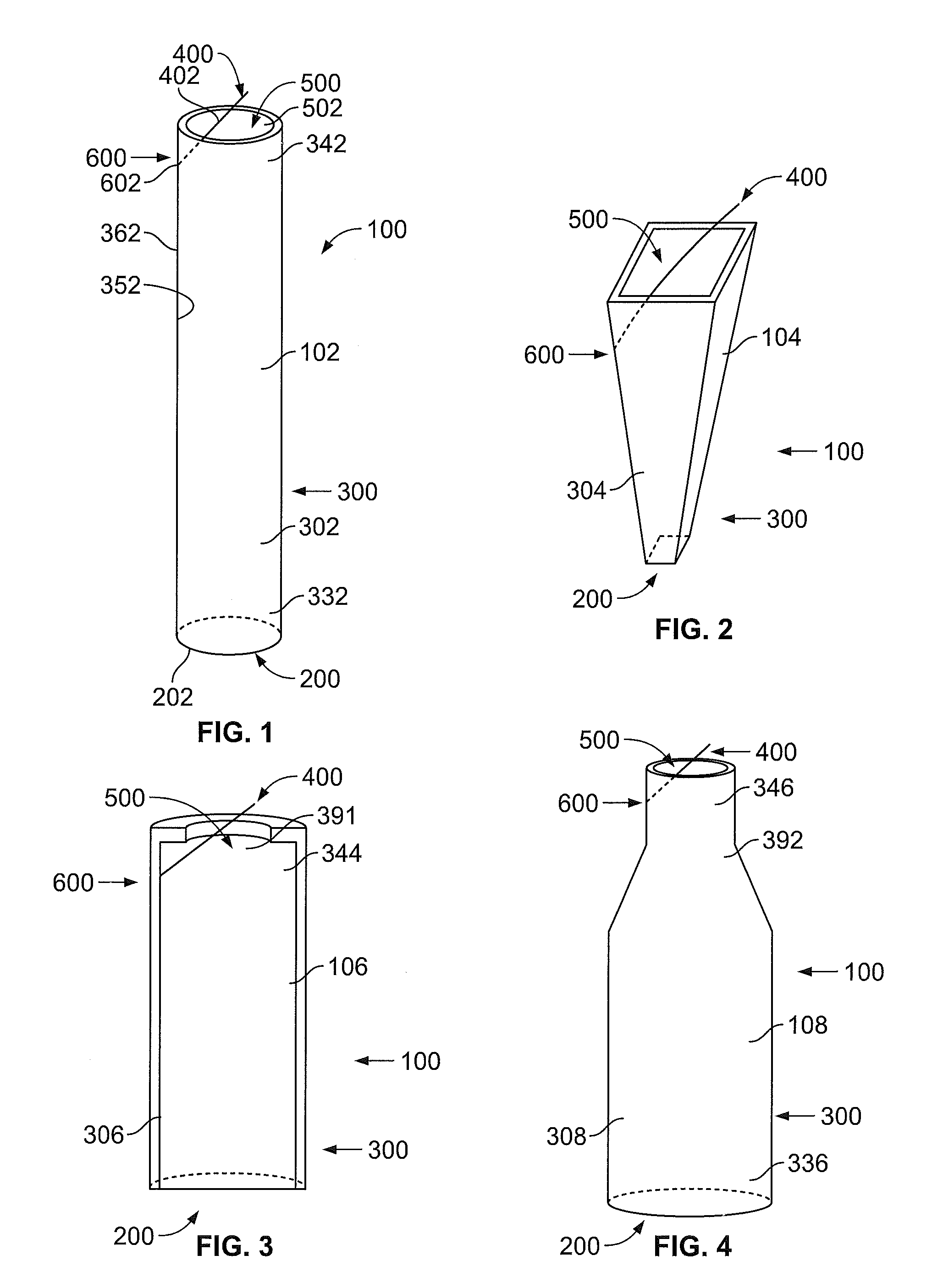
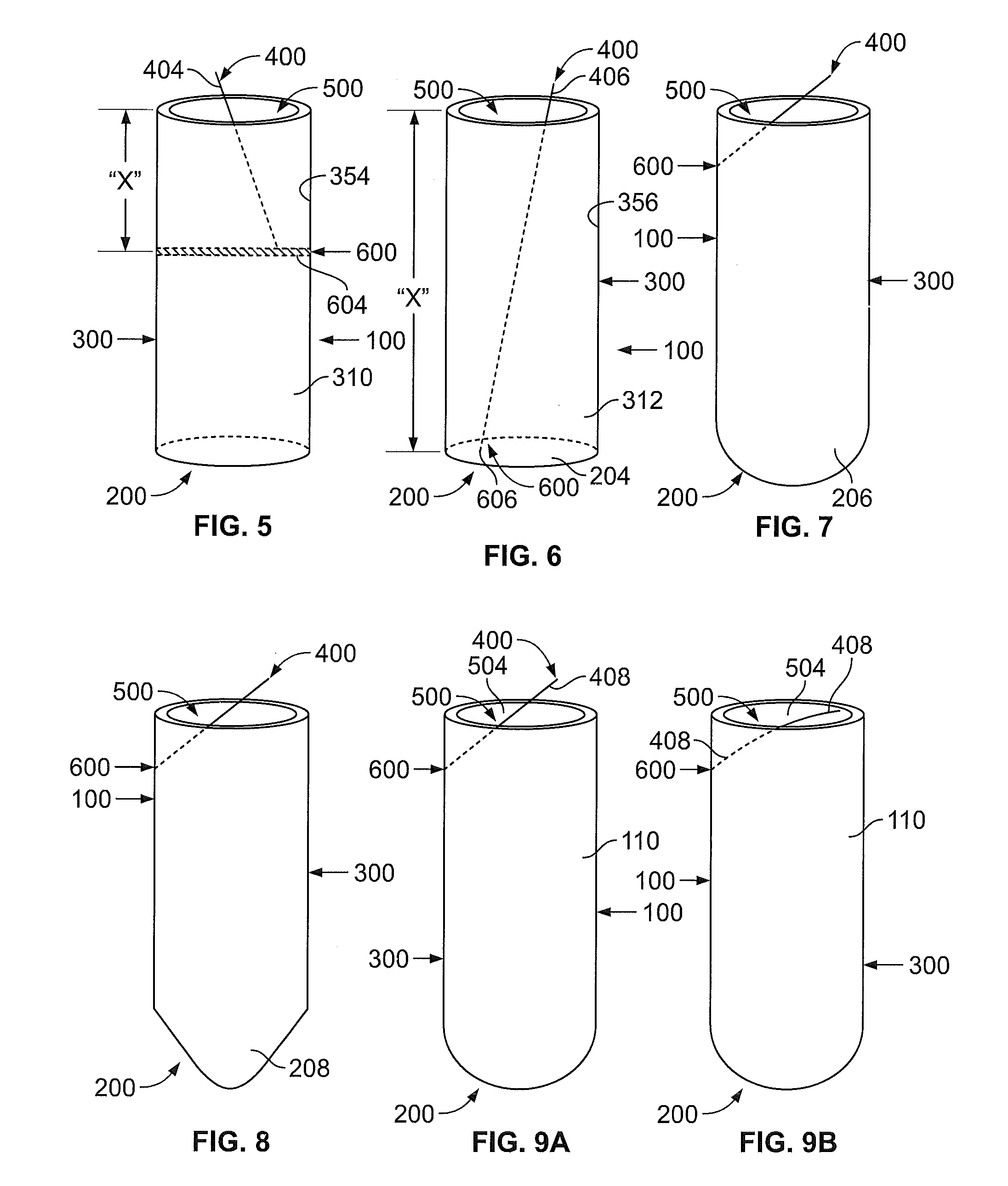
[0056]The present invention relates to a CSF collection tube. As shown generally in FIG. 1, the CSF collection tube 100 includes a bottom end portion 200 integrally connected to a tubular sidewall portion 300. The CSF collection tube 100 further includes a filament element 400 that projects through an open end portion 500 of the CSF collection tube 100, and is attached to the CSF collection tube by an attachment element 600.

[0057]As shown more specifically in FIG. 1, one embodiment of a CSF collection tube 102 includes a circular bottom end portion 202 and a circular cross-sectional tubular sidewall portion 302. Tubular sidewall portion 302 has first end 332 and second end 342 as well as an interior surface 352 and an exterior surface 362. The first end 332 of the tubular sidewall portion 302 is sealed to bottom end portion 202 of CSF collection tube 102. The second end 342 of the tubular sidewall portion 302 defines a circular open end portion 502.

[0058]In the embodiment illustrate...


PUM


Abstract

A cerebrospinal fluid (“CSF”) collection tube includes a bottom end portion and a tubular sidewall portion. The tubular sidewall portion has a first end and a second end, the first end being sealed to the bottom end portion and the second end defining an open end portion of the CSF collection tube. The CSF collection tube further includes a filament element that is attached to an interior surface of the tubular sidewall portion and projects through the open end portion of the CSF collection tube. The CSF collection tube may further include a removeable cap.

Description

[0001]This application claims priority from U.S. Provisional Patent Application No. 60 / 844,900 filed on Sep. 15, 2006.FIELD OF THE INVENTION[0002]The subject invention relates, generally, to medical devices and, more particularly, collection tubes for body fluids, such as cerebrospinal fluid.BACKGROUND OF THE INVENTION[0003]A spinal tap is a procedure which takes samples of a patient's cerebrospinal fluid (“CSF”). Spinal taps are performed when the physician suspects that the patient may have increased intracranial pressure (such as in pseudotumor cerebri) or an infection of the central nervous system (such as meningitis or encephalitis). These procedures are often performed in the emergency room but are also performed in a doctor's office or in a hospital setting.[0004]Usually, before beginning a spinal tap procedure, the physician, or another medical professional arranges the contents of a spinal tap “kit” on a tray, positioned next to where the physician will be sitting to perfor...

Claims


Application Information

Patent Timeline
Patent Type & Authority Patents(United States)
IPC IPC(8): A61M5/32A61B5/00B65D81/00A61D5/00
CPCA61B10/0045A61B17/3401A61B2010/0077
Inventor KIZER, ROBERTGROSS, STEPHEN M.
Owner CREIGHTON UNIVERSITY
Why Eureka
Try Eureka