
Rotational position detecting method for AC servomotor and simple encoder

a technology of ac servomotor and rotational position detection, which is applied in the direction of motor/generator/converter stopper, dynamo-electric converter control, program control, etc., can solve the problem of increasing the cost of the encoder and the motor into which the encoder is built, and the need for high-precision encoder plates and other expensive components, so as to achieve the effect of small installation spa

Active Publication Date: 2012-07-31
HARMONIC DRIVE SYST IND CO LTD
View PDF7 Cites 1 Cited by
  • Summary
  • Abstract
  • Description
  • Claims
  • Application Information

AI Technical Summary

Benefits of technology

The present invention provides a method for accurately detecting the rotational position of an AC servomotor with a low-resolution structural component, such as a simple encoder, and a small installation space. The method uses a magnetic pole detector and a signal processing circuit to detect the rotational position of the motor shaft by analyzing the magnetic pole positions and the phase difference of a three-phase square wave signal generated by the detector. The method can be used with both three-phase and two-phase AC servomotors. The estimated rotational position of the motor shaft is outputted as the rotational position of the motor in a rotational section between edges of the square wave signals. The method is cost-effective and requires minimal space for installation.

Problems solved by technology

A high-precision encoder plate and other expensive components are also necessary.
As a result, it is sometimes difficult to maintain a space for building an encoder into a flat motor or the like having a short shaft length.
The cost of the encoder and the motor into which the encoder is built also increase.

Method used


Image

  • Rotational position detecting method for AC servomotor and simple encoder
  • Rotational position detecting method for AC servomotor and simple encoder
  • Rotational position detecting method for AC servomotor and simple encoder

Examples


Embodiment Construction

[0027]Embodiments of the AC servomotor system to which the present invention is applied will be described hereinafter with reference to the drawings.

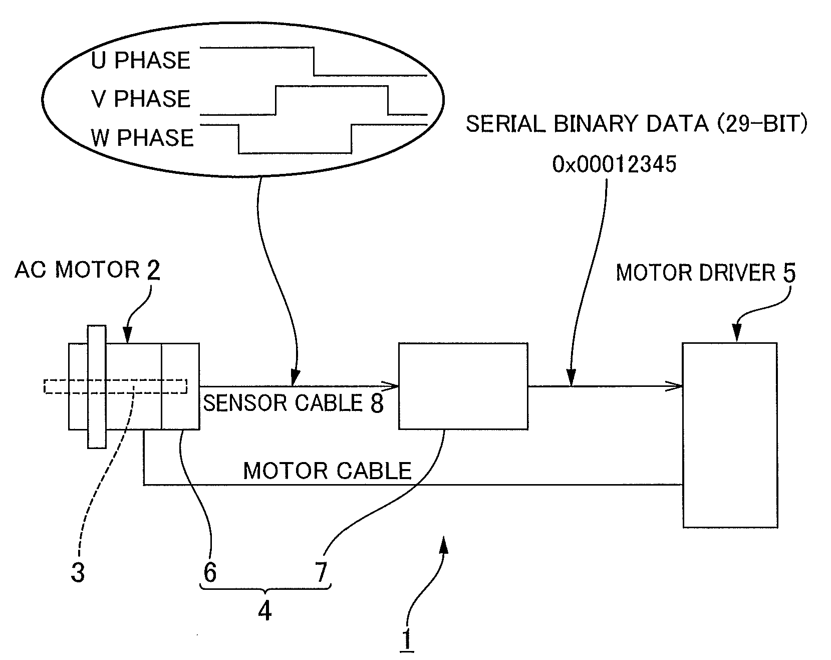
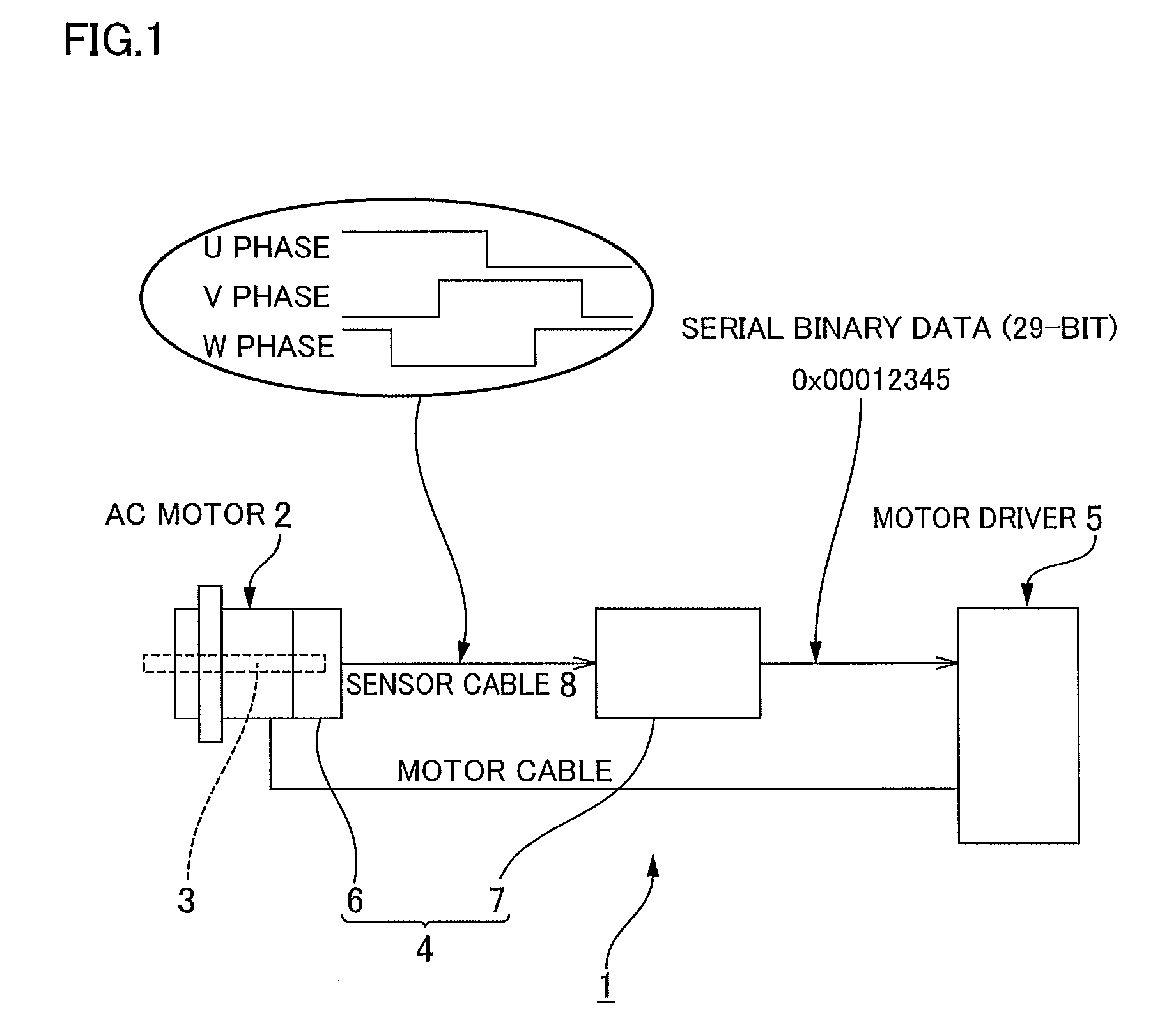
[0028]FIG. 1 is a schematic structural view showing the AC servomotor system. The AC servomotor system 1 has a three-phase AC servomotor 2; a simple encoder 4 for detecting the rotational position of a motor shaft 3 of the AC servomotor 2; and a motor driver 5 for driving and controlling the speed of the AC servomotor 2 on the basis of the output of the simple encoder 4. The AC servomotor 2 is a 20 pole motor, for example.

[0029]The simple encoder 4 is an incremental-type encoder in which the resolution of one turn of the motor rotational shaft is 8192 (13 bits), and the multi-turn count is 16-bit, for example. The rotational position data are outputted and fed to the motor driver 5 in the form of serial binary data composed of a total of 29 bits, including 13 bits of data indicating the rotational position within a single rotation, and ...


PUM


Abstract

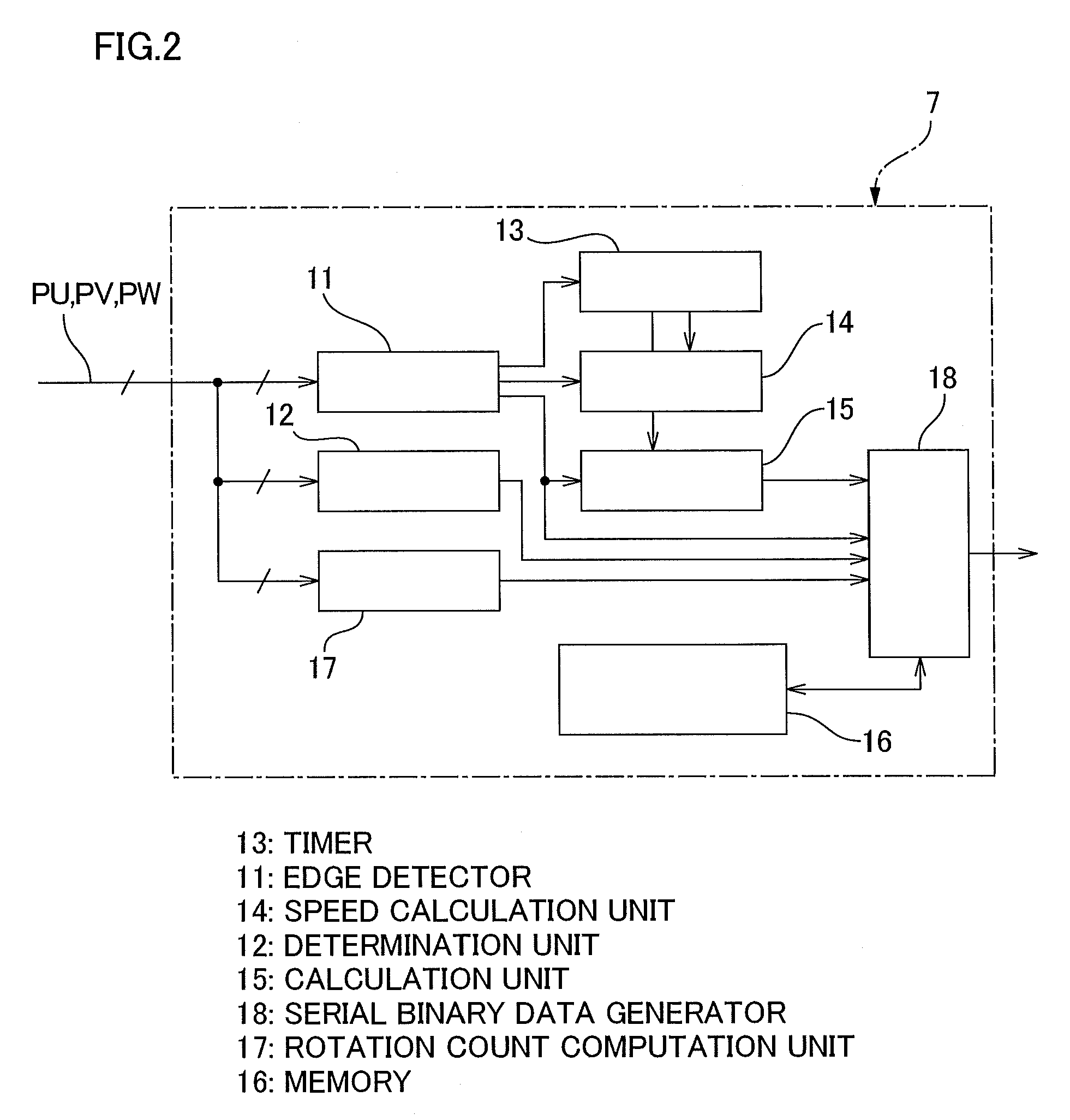
A motor rotational position detecting method detects the magnetic pole position of each phase of a three-phase AC servomotor, generates a three-phase square wave signal having a phase difference of 120 degrees, allocates data on the rotational position of a motor shaft to the edge of each square wave signal, calculates the rotational speed of the motor on the basis of the elapsed time from the previous edge detection point to this time edge detection point, and estimates the rotational position of the motor shaft at a certain period and outputs it on the basis of the rotational speed of the motor and the rotational position allocated to this time edge in the rotational section from this time edge detection point to the next edge detection point. As a result, a detection mechanism can be constructed with a small installation space and at low cost and the output of a high-resolution encoder can be obtained in a pseudo manner.

Description

TECHNICAL FIELD[0001]The present invention relates to a method for detecting a rotational position of a AC servomotor, whereby the rotational position of a motor shaft can be detected using a simple detection mechanism for such purposes as controlling the speed of an AC servomotor, and to a simple encoder that employs this method.BACKGROUND ART[0002]Incremental-type encoders and absolute-type encoders for detecting the rotational position of the motor shaft of an AC servomotor require an optical or magnetic detector in order to ensure a predetermined resolution. A space for providing the detector must therefore be maintained at the rear end portion of the motor rotational shaft or elsewhere. A high-precision encoder plate and other expensive components are also necessary. As a result, it is sometimes difficult to maintain a space for building an encoder into a flat motor or the like having a short shaft length. The cost of the encoder and the motor into which the encoder is built al...

Claims


Application Information

Patent Timeline
Patent Type & Authority Patents(United States)
IPC IPC(8): G05B19/29H02P6/16
CPCG01P3/481G01P3/487G01P3/489G05B19/401G05B2219/37155G05B2219/37163
Inventor SASAKI, KOZO
Owner HARMONIC DRIVE SYST IND CO LTD
Learn More