Sensor circuits

a technology of sensor circuits and circuits, applied in the field of sensor circuits, can solve the problems of inability to meet the needs of low-voltage integrated circuit design, and inability to meet the needs of low-voltage applications

Inactive Publication Date: 2012-07-31
TOUMAZ TECH
View PDF13 Cites 127 Cited by
  • Summary
  • Abstract
  • Description
  • Claims
  • Application Information

AI Technical Summary

Problems solved by technology

However, because Vout varies with, for example, analyte concentration and time, the work potential VRW is subject to fluctuations.
The fluctuations of the work potential VRW away from Vref are a problem with sensor circuit designs such as that of FIG. 1 as they are detrimental to an efficient reaction at the work electrode W and also impact on the consistency of the output signal.
However, this would be too large for a single chip low power integrated circuit design running at low voltages of 1V and below.
However, using two parallel circuits increases the used chip area and therefore the costs of producing the chip.
In addition to this, the design in FIG. 2 would still not solve the problem caused by fluctuations in the work potential VRW.
A further problem which arises with the designs of both FIG. 1 and FIG. 2 is the presence of Shott noise which results from the current sensing resistor.
This noise is proportional to the value of the resistance and will be significant relative to the output voltage.

Method used


Image

  • Sensor circuits
  • Sensor circuits
  • Sensor circuits

Examples


Embodiment Construction

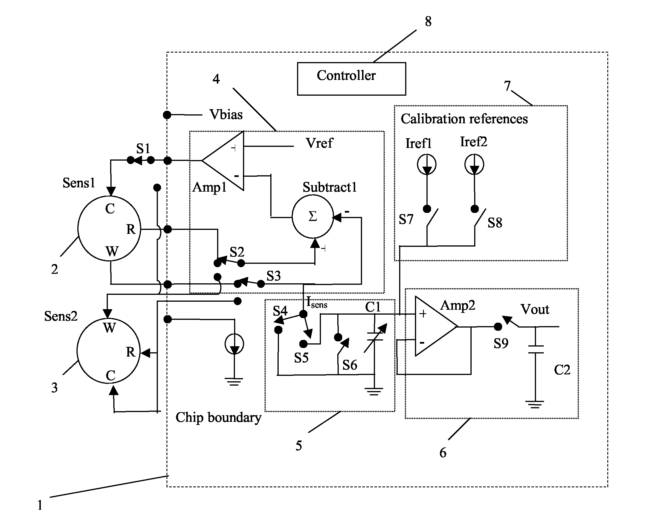
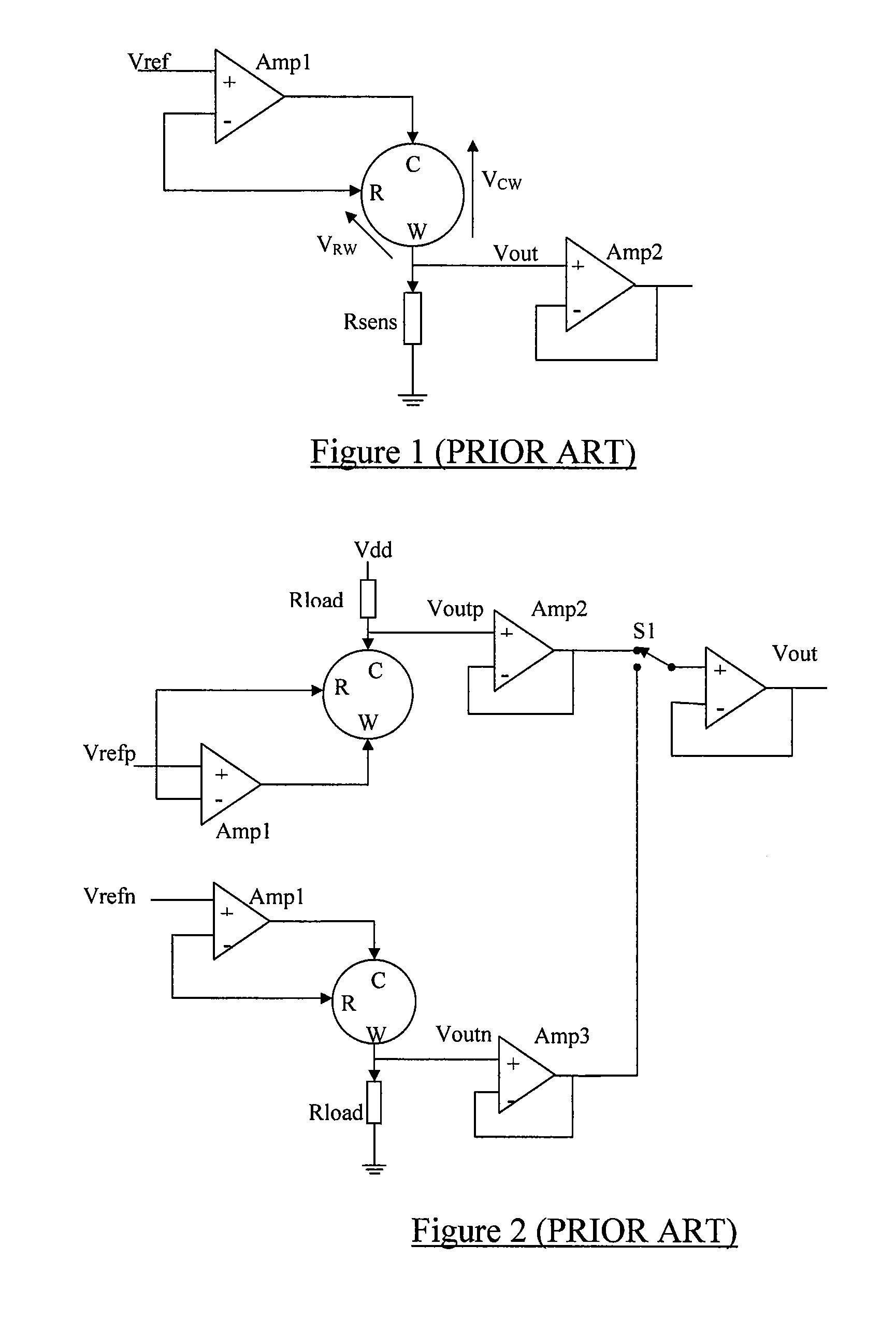
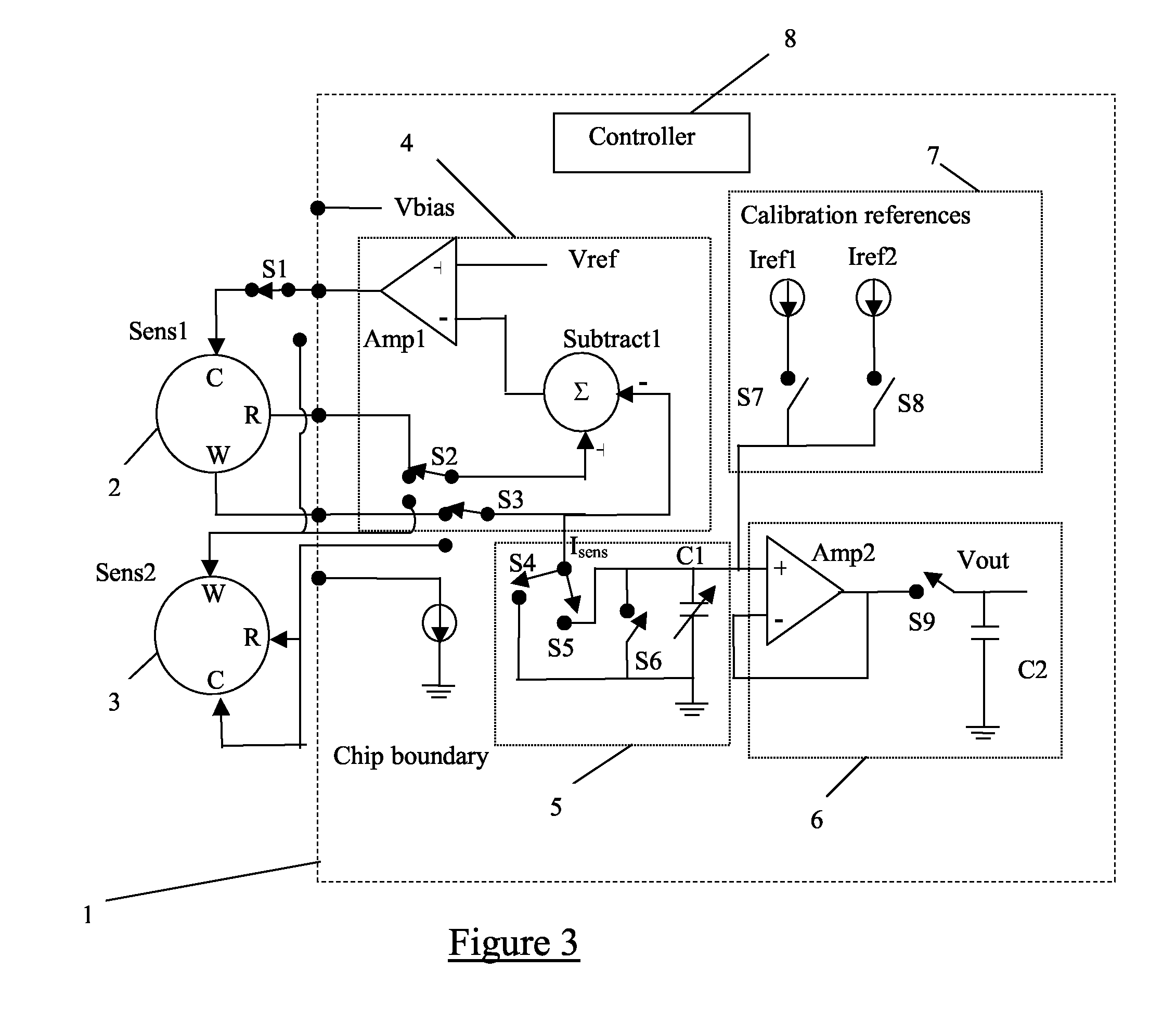
[0043]The amperometric sensor biasing and output circuit to be described replaces the external current sensing resistor of prior art designs (Rsens of FIGS. 1 and 2) with an on-chip variable capacitor. Such a circuit is illustrated in FIG. 3. It is assumed that the circuit has available to it a supply voltage of only one volt or less.

[0044]The circuit is assumed to be integrated into a silicon substrate 1 with two external sensors, Sens1 (reference 2) and Sens2 (reference 3), suitably connected to it; for example sensor Sens1 could be a glucose sensor with an optimal work potential of 0.6V, and sensor Sens2 could be an oxygen sensor with an optimal work potential of −0.6V. However, the sensors 2,3 do not necessarily need to be off-chip and could alternatively be integrated on-chip. Each sensor has a work electrode W, a reference electrode R and a counter electrode C.

[0045]A work potential setting circuit 4 comprises a work potential setting amplifier Amp1 and a subtractor Subtract1....


PUM


Abstract

A circuit for operating an amperometric sensor having a reference electrode, a counter electrode and a work electrode. The circuit comprises an amplifier having a positive input and a negative input and an output. The positive input is coupled to a reference voltage source, and the negative input and the output are coupled together via a negative feedback loop. The circuit includes means for coupling the amperometric sensor into said negative feedback loop of the amplifier wherein, in a first configuration, the counter electrode is coupled to said output and the reference electrode is coupled to said negative input and, in a second configuration, the work electrode is coupled to said output and the reference electrode is coupled to said negative input.

Description

FIELD OF THE INVENTION[0001]The present invention relates to sensor circuits and in particular, though not necessarily, to biasing circuits for amperometric sensors.BACKGROUND TO THE INVENTION[0002]Amperometric sensors have been used to detect the presence of specific analytes, for example enzymes in liquids, for over 20 years. The basic principle is to effect a reaction between the analyte to be detected in a sample and the sensor surface. The subsequent charge produced is then converted into a sensor current that can be measured. The size of the current is generally related to the quantity of analyte present.[0003]FIG. 1 shows a simplified biasing circuit used in a typical sensor. The circuit consists of three electrodes, a counter electrode C, a work electrode W and a reference electrode R. The counter electrode C and reference electrode R are connected to a work potential setting amplifier, Amp1, and an output buffer amplifier, Amp2, and a current sensing resistor, Rsens as show...

Claims


Application Information

Patent Timeline
Patent Type & Authority Patents(United States)
IPC IPC(8): G01R27/08
CPCG01N27/404G01N27/414G01N27/49
Inventor BURDETT, ALISONPADDEN, PAULTOWNSEND, DAVIDTHORNTON, LEGAL REPRESENTATIVE, SHARON LOUISETOWNSEND, LEGAL REPRESENTATIVE, CHRISTOPHER DAVIDMARTIN, LEGAL REPRESENTATIVE, RICHARD ANDREW
Owner TOUMAZ TECH
Why Eureka
Try Eureka