Floor cleaning machine

a cleaning machine and floor technology, applied in the field of floor cleaning machines, can solve the problems of limited cleaning speed, limited or no view on the working area, and even further reduction of cleaning speed during the cleaning process, and achieve the effect of high mobility

Active Publication Date: 2012-08-07
JOHNSONDIVERSEY INC
View PDF18 Cites 9 Cited by
  • Summary
  • Abstract
  • Description
  • Claims
  • Application Information

AI Technical Summary

Benefits of technology

[0006]It is thus an object of the present invention to provide a floor cleaning machine which combines the advantages of “ride-on” and “walk-behind” systems without being subject to their problems and which takes into account the special requirements for indoor floor cleaning machines such as light weight, high mobility etc.
[0007]This is achieved by a floor cleaning machine with the features as described in claim 1. The present invention discloses an apparatus which uses the “ride-on” machines' feature that the operator is placed on the machine in order to enhance the cleaning speed and permit a backward movement. Since, according to the present invention, the operator is standing on the machine at a certain height—instead of sitting on it as in conventional “ride-on” machines—he has a better view on the working area and the whole machine is considerably smaller and more versatile than prior art “ride-on” machines.

Problems solved by technology

Firstly, the cleaning speed is limited because the machine has to be moved by the operator, and due to the tiring of the operator, the cleaning speed will be even further reduced during the cleaning process.
Furthermore, the operator walks behind the machine and thus has only limited or no view on the working area.
As a consequence, the cleaning of edges and a precise steering is difficult—this can be the cause for damages on the machine as well as on the furnishing.
However, due to the rotating cleaning members, the machine tends to deflect from the desired moving direction which imposes additional problems on the manual steering—EP 0 788 761 addresses this problem.
Finally, a backwards approach to walls for picking up cleaning solution and dirt is difficult if not impossible.
Firstly, in contrast to “walk-behind” machines, “ride-on” machines are very space-consuming because they have to be large enough such that the operator can sit on them on a driver's seat.
Furthermore, it is very uncomfortable for the operator to jump on and off the machine to get things out of the way or pick up debris etc.
However, due to the above mentioned construction of the hydrostatic motors, the operator has to pre-select the moving direction of each motor—this results in a considerable rumbling when changing the driving direction of a motor.
Thus, this kind of drive is not suitable for indoor use, and in particular not for cleaning purposes.

Method used


Image

  • Floor cleaning machine
  • Floor cleaning machine
  • Floor cleaning machine

Examples


first embodiment

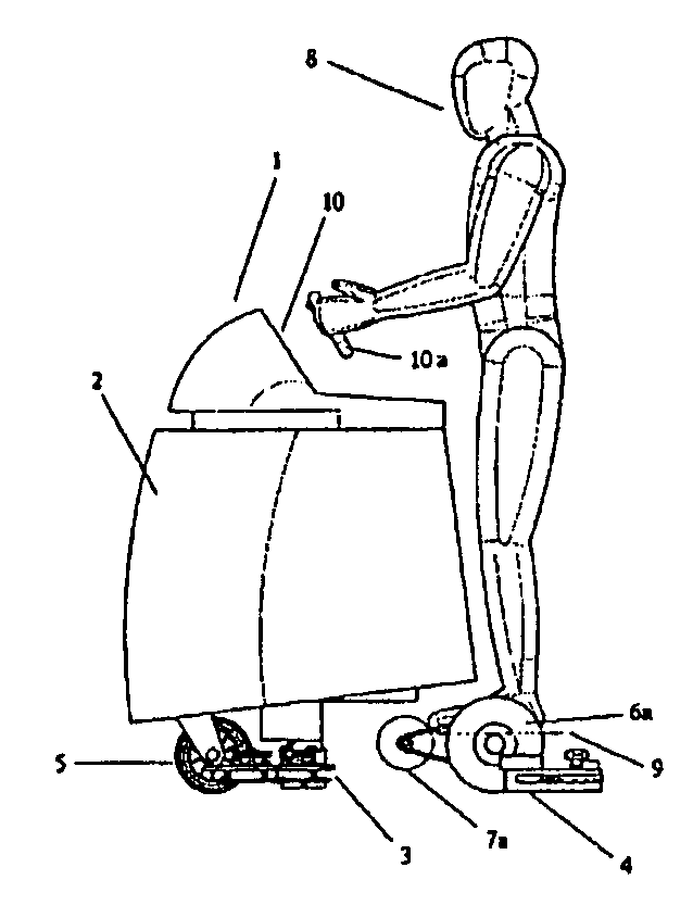
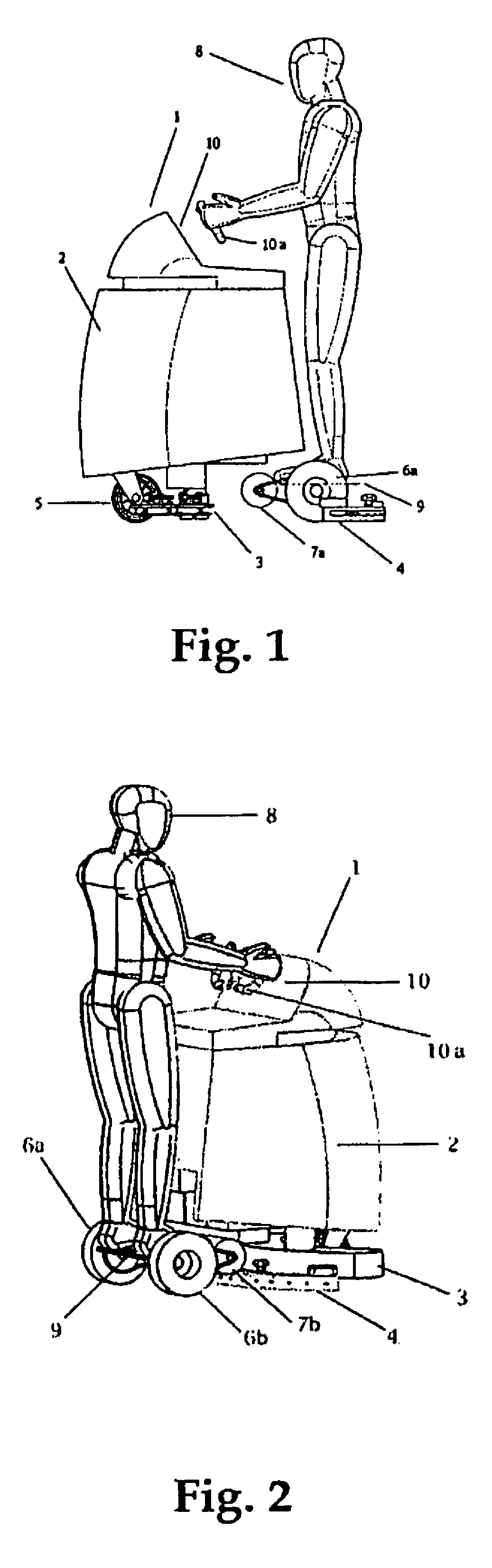
[0014]FIGS. 1, 2 and 3 illustrate the construction of the floor cleaning machine according to the present invention. The cleaning system of the floor cleaning machine 1 comprises a tank 2, a brush unit 3 and a suction foot (squeegee) 4 behind the brush unit. The machine runs on a front castor wheel 5 and two powered rear wheels 6a and 6b which are independently driven by two drive motors 7a and 7b, resp. It is noted that the squeegee 4 can be located behind the rear wheels 6a and 6b (FIG. 1) as well as in front of them (FIG. 2)—the different locations do neither affect the cleaning results nor the movability / moving behaviour of the machine. Thus, in order to give a better view on the rear side of the machine, in FIG. 2 the squeegee 4 is shown in front of the rear wheels 6a, 6b. The wheels 6a, 6b are connected to their respective motors 7a, 7b by a belt or a chain, but other connections can also be used, f.e., hub motors. An operator 8 is standing on a platform 9 behind the tank and ...

third embodiment

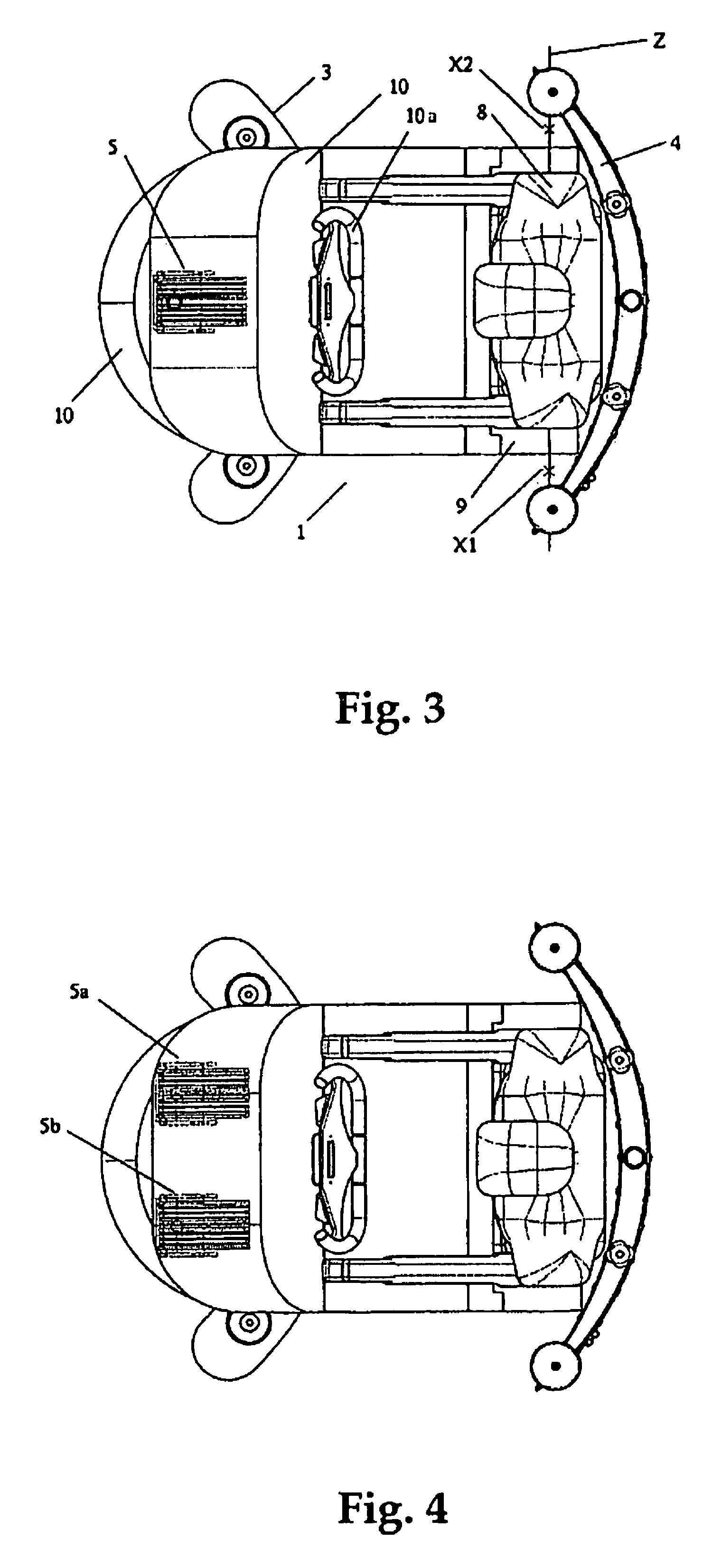
[0021]In FIG. 5, a third embodiment is shown, wherein front wheel 5′ is steered and powered by a drive 7, and the rear wheels 6a′ and 6b′ (not shown) are independently suspended but not driven. Since a reverse drive of the two rear wheels 6a′ and 6b′ is missing in this embodiment, the floor cleaning machine is either turned around the centre of rotation X1 or around the centre of rotation X2. Thus, the same considerations concerning the location of platform 9 for the operator apply.

[0022]As can easily be seen from the above description, due to its feature of the operator standing on a platform on the machine, the floor cleaning machine according to the present invention leads to enhanced cleaning speed and permits a backward movement. Since the operator is standing on the machine—instead of sitting on it—he has a better view on the working area and the whole machine is considerably smaller and more versatile than prior art “ride-on” machines. The operator's view on the working area ...


PUM


Abstract

Floor cleaning machine 1, comprising a cleaning system 2, 3, 4, at least one front wheel 5; 5′; 5a, 5b as well as two rear wheels 6a, 6b, 6a′, 6b′ and a drive mechanism 7; 7a, 7b, wherein the drive mechanism is an electric mono wheel drive and wherein the operator 8 is placed on the machine, characterized in that the operator is standing on a platform 9 which is located above the geometrical axis Z between the two rear wheels, wherein the maximum vertical distance between the platform and the floor is 200 mm. The front wheel can be a castor wheel 5 and the rear wheels 6a, 6b can be independently driven by drive motors 7a, 7b—instead of one castor wheel, two independent castor wheels 5a, 5b can be provided. The front wheel can also be a steered wheel 5′ which is powered by a drive 7 and the rear wheels 6a′, 6b′ can be independently suspended and not driven.

Description

TECHNICAL FIELD[0001]The present invention relates to a floor cleaning machine according to the preamble of claim 1.BACKGROUND AND STATE OF THE ART[0002]Various powered floor cleaning machines are known in the art, and they can be divided into the following two categories: in the first case, the operator is standing on the floor and walking behind the machine (“walk-behind” machines), in the second case, the operator is sitting on the machine itself (“ride-on” machines). Both systems have advantages and drawbacks.[0003]Having the advantage of being space-saving and flexible in handling, “walk-behind” machines like the ones disclosed, f.e., in EP 0 788 761 and 1 262 138 have the following drawbacks, though. Firstly, the cleaning speed is limited because the machine has to be moved by the operator, and due to the tiring of the operator, the cleaning speed will be even further reduced during the cleaning process. Furthermore, the operator walks behind the machine and thus has only limi...

Claims


Application Information

Patent Timeline
Patent Type & Authority Patents(United States)
IPC IPC(8): E01H1/08A47L7/00A47L11/28A47L11/40
CPCA47L11/28A47L11/4061A47L11/00A47L11/4066A47L11/4072A47L11/40
Inventor MAYER, HEINRICH-TITO
Owner JOHNSONDIVERSEY INC
Why Eureka
Try Eureka